
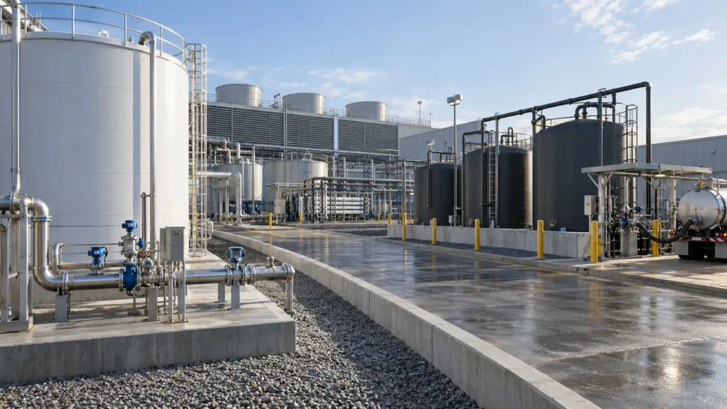
Compare liquid and solid residual routes before selecting the treatment intensity needed to reach them.
Controlled principleA treatment train is not selected until every routine and non-routine liquid, sludge, solid, cleaning waste and off-spec output has a named destination. The endpoint determines the required volume, chemistry, physical form, reliability and monitoring—and therefore how far concentration must proceed. |
|---|
11.1 The endpoint sets treatment intensity
Chapter 10 established that safe residual disposal is a legitimate hierarchy level and that complete ZLD is justified only after upstream options and residual routes have been tested. Chapter 11 makes the endpoint explicit. The question is not simply where the final brine goes. It is which stream, at what flow and composition, in what physical form, under which legal and contractual conditions, with what contingency and long-term liability.
A low-cost receiving route may allow the project to stop at MLD. A route with strict acceptance limits may require selective removal, greater volume reduction or conversion to a solid. A route that exists geographically but has no available capacity, no permit path, no compatible receiving process or no credible outage alternative is not an endpoint.
The endpoint should be selected on the same normal, design, turndown and worst-credible cases developed in Chapters 6–9. Average annual flow is useful for economics, but capacity, storage and upset management depend on duration and peak load. The route must also survive changes in regulation, weather, receiver operation, transport availability, closure obligations and the waste’s legal classification.
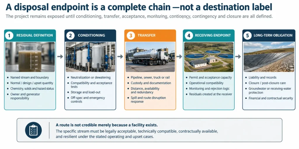
Figure 11.1. A credible endpoint includes conditioning, transfer, acceptance, contingency and lifecycle obligations.
| Endpoint field | Minimum definition | Design consequence | Commercial / legal proof | Failure if omitted |
|---|---|---|---|---|
| Named residual | Stream origin, boundary, physical form, quantity, chemistry, variability and hazard status. | Defines conditioning, storage, materials and capacity. | Waste classification and analytical acceptance basis. | The receiving route is evaluated for the wrong stream. |
| Named receiver | Outfall, sewer authority, injection formation/well, pond, mine facility, landfill, user or treatment hub. | Sets transfer and interface requirements. | Permit, letter of acceptance, capacity reservation or contract path. | A generic route is treated as available without evidence. |
| Acceptance envelope | Flow, load, pH, temperature, solids, organics, toxicity, radioactivity and prohibited constituents. | Defines pretreatment and recovery target. | Current permit/criteria and sampling method. | Treatment either underperforms or over-treats. |
| Availability and capacity | Routine capacity, peak acceptance, maintenance windows and remaining life. | Sets storage, redundancy and expansion timing. | Capacity study and service-level commitments. | Receiver outage becomes an unplanned site shutdown. |
| Transfer system | Pipeline, sewer, truck, rail or onsite conveyance; custody and loss points. | Pumping, loading, materials, route and spill controls. | Transport authorization and responsibility matrix. | Logistics or transfer losses dominate actual risk. |
| Residuals at receiver | Sludge, leachate, pond salts, tailings water, purge, off-gas or rejected loads. | May require additional treatment or return streams. | Receiver residual route and liability allocation. | Burden is transferred but not resolved. |
| Contingency | Upset storage, alternate route, curtailment or safe shutdown. | Sets tankage and operating philosophy. | Approved fallback and trigger conditions. | A single-point failure invalidates claimed availability. |
| Closure / post-closure | Final inventory, monitoring, remediation and financial responsibility. | Adds lifecycle cost and design provisions. | Permit, closure plan, security and records. | Near-term unit cost hides long-term obligation. |
Table 11.1. Minimum information required before a residual route can be called a credible endpoint.
Regulatory boundaryThe examples below use current U.S. federal sources to show how direct discharge, sewer discharge, injection, transport and land disposal are structured. They are not legal opinions and do not replace the applicable national, state, provincial, basin, municipal, mining or waste permit. The project must verify the current jurisdiction and facility-specific conditions. |
|---|
11.2 Surface, sewer and marine discharge
Direct surface-water and marine discharges are point-source routes. In the United States, industrial discharges require NPDES authorization with technology-based and, where needed, water-quality-based limits. A marine outfall remains a Clean Water Act discharge; EPA states that land-based outfall effluent entering ocean waters is regulated through NPDES and the ocean-discharge criteria rather than being exempt from environmental review.
Indirect sewer discharge is a different interface. The receiving publicly owned treatment works must be protected against pass-through, interference, damage, worker hazards and contamination of its sludge or receiving water. EPA’s pretreatment rules apply general and specific prohibitions to nondomestic users, while local limits reflect the actual capacity and constraints of the receiving POTW. A sewer connection therefore cannot be screened from pipe diameter and tariff alone.
For saline streams, the project should test hydraulic capacity, chloride/TDS or conductivity constraints, metals and organics, temperature, pH, sulfide and gas release, solids deposition, biological inhibition, corrosion, receiving-water mixing and seasonal low-flow conditions. Marine dilution or co-discharge does not remove persistent contaminants, heat, density effects or chemical additives; the permitted mixing zone and ecological basis must be demonstrated.
| Route | Primary gate | Key site evidence | New residual / risk | Reason to intensify treatment |
|---|---|---|---|---|
| Surface-water discharge | Permit limits, receiving-water assimilative capacity and discharge reliability. | Effluent and receiving-water data, seasonal flow, mixing, load allocation and monitoring plan. | Receiving-water impact, permit exceedance, diffuser/outfall maintenance and storm/upset storage. | Required flow/load reduction or removal of a limiting constituent. |
| Sewer / POTW | POTW acceptance, general/specific prohibitions, local limits and hydraulic/process capacity. | Industrial-user control mechanism, load profile, slug control, tariff and receiver residuals. | Pass-through, interference, corrosion, gas release, POTW sludge contamination and rejection. | Acceptance limits or capacity make the untreated stream incompatible. |
| Marine outfall | NPDES/ocean criteria or applicable coastal authorization, diffuser performance and sensitive-receptor protection. | Bathymetry, currents, density plume, ecology, chemical additives, temperature and monitoring. | Benthic salinity/density exposure, chemical accumulation, outfall failure and public/stakeholder risk. | Environmental or permit conditions require lower flow, lower load or altered chemistry. |
Table 11.2. Direct, indirect and marine discharge are separate endpoints with different receivers and failure modes.
11.3 Deep-well injection
Deep-well injection can accept substantial liquid volumes where suitable geology, well construction and a regulatory pathway exist. Under the U.S. UIC programme, Class I wells inject hazardous or non-hazardous industrial and municipal wastes into deep, confined formations below underground sources of drinking water. EPA identifies siting, construction, operating pressure, monitoring, mechanical integrity, reporting and closure as core permit requirements.
The endpoint is therefore geological infrastructure, not a disposal pump. The project must establish formation capacity and injectivity, confining layers, compatibility between the fluid and formation, scaling or precipitation in the well, corrosion, seismic and pressure effects, existing well penetrations, monitoring and the consequences of lost injectivity. Hazardous-waste injection adds land-disposal restrictions and a demonstration that the waste will remain isolated for the regulated period.
| Injection gate | Evidence required | Design implication | Failure / contingency |
|---|---|---|---|
| Geological suitability | Injection zone, confining sequence, faults, nearby wells and area of review. | Well depth, casing, cementing and allowable pressure. | No suitable formation or migration pathway; route unavailable. |
| Injectivity and capacity | Formation testing, pressure response, anticipated life and competing users. | Number of wells, pump duty, redundancy and expansion. | Declining injectivity, pressure limit or premature capacity loss. |
| Fluid compatibility | Speciation, solids, gas, corrosion and fluid-rock interaction. | Filtration, pH control, antiscalant compatibility and materials. | Wellbore scale, plugging, corrosion or induced precipitation. |
| Integrity and monitoring | Mechanical-integrity tests, annulus monitoring, sampling and records. | Instrumentation, test intervals and shutdown logic. | Automatic curtailment, repair or alternate endpoint. |
| Closure and liability | Plugging plan, financial assurance and long-term records. | Lifecycle allowance and responsibility. | Stranded well, contamination claim or extended monitoring. |
Table 11.3. Deep-well injection is controlled by geology, injectivity, fluid compatibility and lifecycle assurance.
11.4 Evaporation ponds
Evaporation ponds convert a liquid-management problem into a land, climate, wildlife, seepage, salt-inventory and closure problem. Reclamation’s concentrate-management work treats ponds as one site-specific option among multiple routes and recommends planning-level screening followed by desktop studies and pilot or site testing. Separate Reclamation projects note that pond size and environmental impact can become critical for inland desalination.
The water balance must use local net evaporation, rainfall, storm events, seepage allowance, freeboard and seasonal storage—not an annual evaporation number alone. The salt balance must identify precipitation sequence, crust formation, windblown salt, dust, wildlife exposure, liner compatibility, leachate, dredging or harvesting, final solids destination and closure. Organics, metals and contaminants of emerging concern can concentrate in the pond even when the salinity balance appears manageable.
| Pond issue | Minimum data | Design response | Residual created | Reason route may fail |
|---|---|---|---|---|
| Climate and water balance | Monthly evaporation, precipitation, storm, humidity, wind and temperature. | Area, depth, cells, freeboard and seasonal inventory. | Stored brine and rainfall/storm water. | Insufficient net evaporation or extreme-weather exposure. |
| Land and hydrogeology | Available area, geotechnical data, groundwater, flood and seismic conditions. | Liner, leak detection, berms, drainage and monitoring. | Potential seepage and contaminated soil/liner. | Land unavailable, groundwater risk or permitting constraint. |
| Salt and solids | Phase sequence, settling, crust, dust and harvest properties. | Cell rotation, dredging, drying, equipment access and storage. | Mixed salts, wet solids and wash water. | No acceptable solids route or pond loses working volume. |
| Ecology and air | Wildlife use, toxicity, odour, aerosols and windblown salt. | Deterrence, covers/barriers, dust and monitoring controls. | Wildlife exposure, salt deposition and off-gas/odour. | Unacceptable ecological or community impact. |
| Closure | Final liquid/solid inventory, liner, contaminated media and financial responsibility. | Closure sequence, final cover/removal and post-closure monitoring. | Large legacy inventory. | Closure liability overwhelms apparent operating simplicity. |
Table 11.4. Evaporation ponds require simultaneous water, salt, land, ecological and closure balances.
11.5 Off-site hauling
Hauling is flexible and can be rational for low-volume, episodic, hazardous or highly variable streams. It can also become an expensive and fragile routine endpoint when the residual volume grows. The project must name the receiving facility, accepted waste profile, transport mode, route, loading interface, custody, rejection procedure, emergency response and replacement capacity.
For U.S. hazardous waste, EPA’s manifest system tracks the waste from the generator to the receiving treatment, storage or disposal facility, and transporters are subject to RCRA and DOT requirements. The manifest confirms custody and destination; it does not transfer the generator’s responsibility for correct characterization or guarantee future receiver availability.
| Hauling control | Minimum proof | Cost / risk driver | Required fallback |
|---|---|---|---|
| Waste profile and acceptance | Current profile, analytical method, frequency and receiver approval. | Testing, rejected loads, profile expiry and off-spec storage. | Second receiver or safe onsite hold. |
| Transport capacity | Licensed carrier, vehicle/container type, daily dispatch capacity and route. | Distance, fuel, waiting, weather, road restrictions and driver availability. | Additional carrier, tankage or production curtailment. |
| Custody and documentation | Manifest or applicable shipping documentation, weights/volumes and signatures. | Administrative control, discrepancy and returned shipments. | Reconciliation and return-load procedure. |
| Loading and safety | Compatible materials, vapour/gas control, spill containment and operator procedure. | Loading time, corrosion, odour, exposure and cleaning. | Emergency isolation and spill response. |
| Receiving-facility continuity | Permit, capacity, operating schedule and contract term. | Price escalation, shutdown, ownership change or acceptance tightening. | Alternative contracted endpoint. |
Table 11.5. Off-site hauling is a logistics and chain-of-custody system, not merely a unit transport rate.
11.6 Tailings integration
Mining projects may propose to place brine, sludge or crystallized salts in a tailings storage or filtered-tailings system. This can be an integrated site solution only when the added liquid and chemistry are included in the tailings facility’s design basis, water balance, geochemistry, seepage and closure plan. A tailings facility is not a free sink for a water project.
The Global Industry Standard on Tailings Management requires lifecycle responsibility, an integrated knowledge base, risk classification, environmental protection, governance, emergency response and disclosure. Adding a saline or chemically reactive stream can change pore-water chemistry, consolidation, dust, seepage, metal mobility, geosynthetic compatibility, return-water quality and closure performance.
| Integration question | Evidence required | Tailings consequence | Water-project consequence | Gate |
|---|---|---|---|---|
| Hydraulic capacity | Annual/peak addition, storm/freeboard basis and return-water circuit. | Pond inventory, saturation, beaching or filtered-tailings moisture. | Storage and transfer limits. | Facility engineer confirms available capacity. |
| Geochemical compatibility | Brine/sludge speciation, tailings mineralogy, leach/seepage tests and redox path. | Metal mobility, precipitation, acid/base reaction and seepage quality. | Pretreatment or segregation requirement. | No adverse lifecycle geochemistry demonstrated. |
| Physical behaviour | Rheology, settling, consolidation, filtration, strength and dust tests. | Deposition, stability, closure surface and trafficability. | Dewatering or solids-form specification. | Geotechnical performance remains compliant. |
| Materials and infrastructure | Pipeline/liner compatibility, corrosion, scaling and plugging. | Transfer and containment reliability. | Materials and maintenance duty. | Operable under normal and upset chemistry. |
| Closure and governance | Closure inventory, monitoring, ownership, disclosure and emergency plan. | Long-term facility liability. | Cost and risk allocation. | Responsible executive and facility owner approve. |
Table 11.6. Tailings integration must pass hydraulic, geochemical, geotechnical and governance gates.
11.7 Solidification and landfill
Solidification changes the physical form of a residual; stabilization aims to reduce contaminant mobility. Neither process automatically destroys the contaminants or creates a saleable product. EPA guidance emphasizes that suitability depends on the waste and that leaching, physical stability and long-term performance must be evaluated.
Landfill acceptance depends on waste classification, free-liquid restrictions, treatment standards, leachability, strength, packaging, landfill type and permit. Under the U.S. hazardous-waste land-disposal restrictions, untreated hazardous wastes generally must meet waste-specific treatment standards before land disposal, and dilution cannot substitute for treatment. Landfills and other land-disposal units may carry closure, leachate, groundwater-monitoring and post-closure obligations.
For saline residues, binders can greatly increase disposal mass and volume, and some salts interfere with cement hydration or remain highly leachable. The process must close binder addition, water demand, heat, gas generation, curing, free liquid, compressive or handling strength, leachate chemistry and the final landfill’s acceptance criteria.
| Gate | Test / evidence | What it proves | New burden | Failure mode |
|---|---|---|---|---|
| Waste classification | Hazardous/non-hazardous determination and applicable treatment standard. | Legal landfill route and required treatment. | Sampling, records and possible hazardous facility. | Wrong landfill or unlawful disposal. |
| Formulation | Binder/absorbent screening, water ratio, compatibility and curing. | Workable and repeatable waste form. | Binder mass, mixing energy and larger disposal volume. | No set, swelling, cracking or gas generation. |
| Free liquid and handling | Applicable free-liquid test, strength and transport durability. | Can be handled and accepted as a solid/nonwastewater form. | Dust, breakage and container requirements. | Rejected load or liquid release. |
| Leachability / durability | Applicable leach tests, ageing, wet/dry and chemical exposure. | Contaminant immobilization under stated conditions. | Long-term monitoring and uncertainty. | High salt/metal release or degradation. |
| Landfill lifecycle | Permit, liner/leachate system, capacity, closure and post-closure provisions. | Final endpoint and responsibility. | Leachate, groundwater monitoring and financial assurance. | Long-term liability exceeds apparent unit fee. |
Table 11.7. Solidification and landfill require legal, physical, leaching and lifecycle acceptance.
11.8 Beneficial industrial reuse
Beneficial reuse can be the strongest endpoint when the residual displaces a real input and the receiving process can control variability. Water may be reused for cooling, washing, dust suppression, process make-up or other fit-for-purpose applications. A salt solution, slurry or solid may be used as a reagent, feedstock, construction input or service only when the technical specification, legal status, environmental performance and receiving user are established.
EPA’s industrial-water-reuse resources emphasize treatment matched to the end use. Its 2026 methodology for industrial non-hazardous secondary materials likewise treats beneficial use as a case-specific evaluation and does not replace existing law or beneficial-use determinations. These principles support a strict rule: a proposed reuse endpoint is not available until the user, specification, quantity, schedule, liability and rejection route are named.
| Reuse endpoint | Receiver proof | Quality proof | Commercial / legal proof | Fallback |
|---|---|---|---|---|
| Internal water reuse | Named process, demand profile, storage and operator ownership. | Fit-for-purpose limits, reliability and upset effects. | Internal transfer value and compliance basis. | Return to treatment, storage or disposal. |
| External industrial water reuse | User demand, connection/transport and service agreement. | Specification, monitoring and responsibility at transfer. | Water/reuse authorization and contract. | Alternate user or disposal. |
| Liquid chemical / brine use | Process stoichiometry, impurity tolerance and consumption rate. | Active concentration, competing ions and consistency. | Product/by-product/waste status and pricing basis. | Off-spec treatment or disposal. |
| Solid material use | Application, user process, annual demand and handling. | Purity, particle size, moisture, leachability and durability. | Beneficial-use determination, buyer qualification and liability. | Qualified landfill or reprocessing. |
Table 11.8. Beneficial reuse is an endpoint only when the receiving user, specification and rejection route are qualified.
11.9 Centralized brine-treatment hubs
A centralized hub can aggregate several industrial residuals, share analytical, treatment, energy, storage and product-qualification infrastructure, and provide a professional operating team. It can also create transport dependency, cross-contamination, contractual complexity and a large common point of failure.
Recent peer-reviewed work on eco-industrial parks describes centralized utility hubs with reuse headers and regeneration units as a practical model for interplant water integration, while a 2024 survey of 86 Chinese industrial enterprises or parks found that park-level uniform wastewater-resource utilization was a significant implementation pathway. These sources support the hub concept, not a universal brine-hub business case.
The hub endpoint must define eligible streams, segregation classes, pretreatment at source, transfer network, tariffs, minimum and maximum commitments, ownership of products and wastes, capacity expansion, quality excursions, shutdown allocation and long-term liability. A hub is most credible when aggregation improves utilization or enables equipment and expertise that no single generator could justify.
| Hub gate | Required evidence | Shared benefit | Shared risk | Contractual control |
|---|---|---|---|---|
| Stream compatibility | Generator-specific chemistry, variability and prohibited combinations. | Segregated treatment trains and higher asset utilization. | One stream destabilizes the common system. | Acceptance classes, source pretreatment and rejection rights. |
| Scale and load factor | Committed annual/peak flows, seasonality and growth. | Larger equipment, specialist operation and redundancy. | Underutilized assets or capacity shortage. | Minimum commitments and expansion triggers. |
| Transfer network | Distance, pipeline/truck/rail options and route resilience. | Shared logistics and monitoring. | Network outage or spill affects multiple sites. | Custody, metering and emergency allocation. |
| Products and residuals | Product specifications, buyers/users, mother liquor and disposal route. | Aggregated volume can improve product qualification. | Mixed impurities create off-spec output. | Ownership, revenue, rejection and liability rules. |
| Governance and bankability | Operator capability, permits, tariffs, guarantees and risk allocation. | Professional service and shared capital. | Counterparty default and common-mode failure. | Long-term service, step-in and closure provisions. |
Table 11.9. Centralized hubs exchange scale and specialist capability for network, compatibility and governance risk.
11.10 Disposal decision matrix
No single endpoint ranks first in all settings. The matrix below is a visual prompt for what site evidence tends to strengthen or weaken each route. It deliberately excludes universal costs and compliance scores. Reclamation’s toolbox similarly warns that default technology assessments and weights are subjective and should be customized, with further desktop and pilot work for cost and performance.
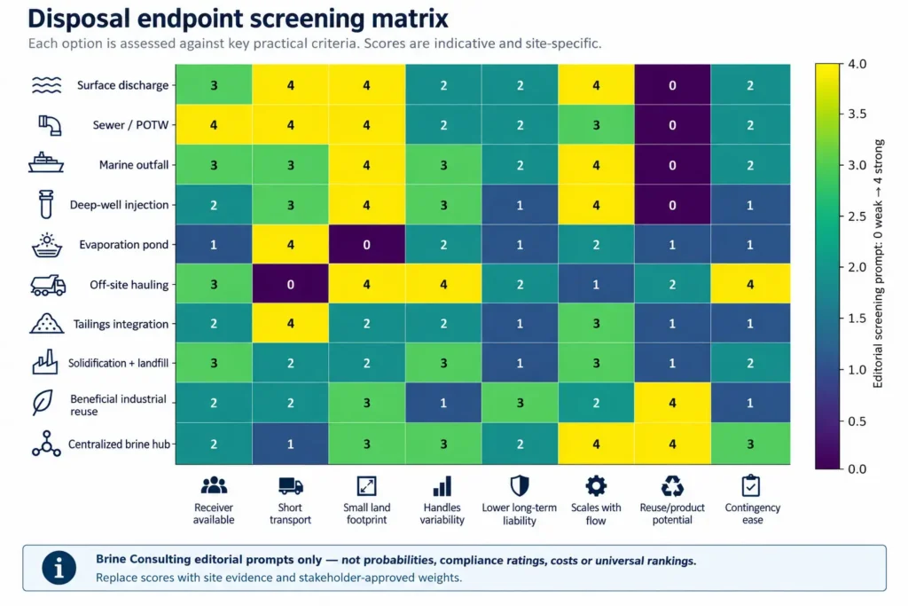
Figure 11.2. Disposal decision matrix. Replace all editorial scores with project evidence and approved weights.
| Decision criterion | Question to answer | Evidence source | Downside case | Decision output |
|---|---|---|---|---|
| Technical compatibility | Can the route accept normal, design and upset physical/chemical conditions? | Analysis, modelling, test, receiver data and operating history. | Higher solids/organics, temperature or incompatible batch. | Accept / condition / segregate / reject. |
| Capacity and availability | Is capacity available for the project life and at peak load? | Permit, facility study, contract, well/pond/landfill/hub life. | Receiver outage, lower capacity or delayed expansion. | Base route, limited route or unavailable. |
| Regulatory path | What approvals, limits, classifications and monitoring apply? | Current jurisdiction-specific legal/permit review. | Tighter limit, reclassification or approval delay. | Permittable / conditional / no credible path. |
| Logistics and infrastructure | How is the residual moved, stored and transferred safely? | Route study, hydraulics, traffic, materials and emergency plan. | Weather, strike, road closure, pipeline failure or spill. | Required redundancy and storage. |
| Environmental and social burden | What receiving-water, groundwater, land, ecology, emissions and community effects remain? | EIA, modelling, baseline and stakeholder evidence. | Sensitive receptor or cumulative impact. | Mitigate / redesign / reject. |
| Lifecycle liability | Who owns monitoring, closure, rejection and future remediation? | Contracts, permits, financial assurance and governance. | Receiver insolvency or long-term release. | Risk allocation and security. |
| Total cost | What is the levelized cost including conditioning, transfer, residuals, availability and closure? | Comparable quotes and visible assumptions. | Higher fee, lower availability, rejected loads and closure extension. | Baseline and sensitivity range. |
| Strategic value | Does the route preserve water, production, product or future options? | Site strategy and quantified value. | User/buyer loss or changed site plan. | Preferred endpoint portfolio. |
Table 11.10. Site-specific criteria for converting endpoint screening into a defensible decision.
11.11 Compare endpoints as a portfolio
A single site may need several endpoints. A steady compatible stream may discharge to sewer, a small hazardous batch may be hauled, softening sludge may be landfilled, recovered water may serve an internal user and an emergency tank may protect all routes during outages. The portfolio must close the annual and peak balances without double counting capacity.
Each route should have a status: baseline, preferred, contingency, temporary, future or unavailable. The team should identify the trigger that changes status, such as a permit date, receiver capacity threshold, flow growth, pond inventory, well pressure, landfill acceptance, transport disruption or completion of a centralized hub.
| Residual stream | Primary endpoint | Conditioning | Capacity / availability | Contingency | Owner / decision status |
|---|---|---|---|---|---|
| Continuous inorganic concentrate | Named permitted route | pH/solids/constituent limits stated | Annual and peak capacity reserved | Storage plus alternate route | Owner; baseline/preferred |
| CIP / regeneration batch | Separate receiver or treatment | Neutralization and event profile | Batch window confirmed | Dedicated tank and delayed dispatch | Owner; episodic |
| Softening sludge | Dewatering plus named landfill/use | Cake specification and wash-water return | Annual tonnage and acceptance | Second facility or storage pad | Owner; qualified/conditional |
| Mother liquor / purge | Named liquid or solid route | Concentration and impurity envelope | Peak purge and upset case | Reduced production or emergency storage | Owner; critical endpoint |
| Off-spec recovered product | Rework, alternate user or disposal | Segregated quarantine | Worst rejection rate included | Qualified disposal route | Commercial owner; downside case |
Table 11.11. Endpoint portfolio register for routine, episodic and off-spec residuals.
Endpoint acceptance gateBefore Chapter 12, each residual must have at least one technically compatible and legally credible endpoint, a current capacity and acceptance basis, a transfer and contingency plan, visible lifecycle liability and a comparable total-cost basis. Where a manageable liquid route remains credible, MLD must be tested before the project assumes complete ZLD. |
|---|
11.12 Handover to when MLD is preferable
Chapter 11 establishes whether the site has a manageable liquid route and what that route costs and constrains. Chapter 12 tests the central MLD question: whether reducing the liquid residual to the route’s capacity or economic optimum delivers most of the project value without paying the disproportionate energy, solids and reliability burden of the final liquid-elimination step.
The handover is an endpoint register with accepted flow and chemistry, full lifecycle cost, availability, contingency and the marginal treatment required to reach it. The final recovery increment must then justify itself against that baseline.
11.13 Chapter conclusion
Every endpoint has site constraints and residual risks. Surface, sewer and marine discharge depend on the receiving water or treatment works and its permit basis. Deep-well injection depends on geology, injectivity, well integrity and closure. Evaporation ponds depend on land, climate, seepage, wildlife, salt inventory and post-closure care. Hauling depends on custody, transport and receiver continuity.
Tailings integration must enter the mine’s hydraulic, geochemical, geotechnical and governance basis. Solidification and landfill require classification, treatment, physical and leaching performance and lifecycle acceptance. Beneficial reuse requires a named user and specification. Centralized hubs can create scale and specialist capability, but introduce compatibility, network and counterparty risk.
The correct endpoint is therefore not the one with the shortest flowsheet or lowest quoted unit fee. It is the route—or portfolio of routes—that remains technically compatible, legally available, operationally resilient and financially credible for every routine and non-routine residual. Once that baseline is known, the project can decide whether MLD is the rational optimum.
Chapter 11 in one sentenceName and qualify the destination of every liquid and solid first; the endpoint determines how much treatment and recovery the project actually needs. |
|---|