
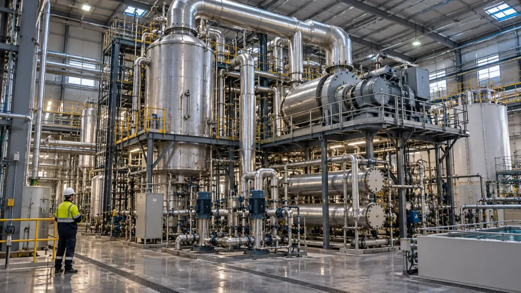
Explain why thermal systems remain important near saturation—and how to minimize their duty without hiding their operating burden.
Controlled principleThermal concentration is justified when the remaining water-removal duty cannot be met more reliably or with lower total system burden by source control, selective removal, membrane or electrochemical concentration, or a managed liquid endpoint. Once justified, the design must minimize external heat while preserving the temperature driving force, heat-transfer surface, condensate quality, materials and residual routes. |
|---|
18.1 Why thermal systems remain important near saturation
Chapter 17 evaluated advanced membranes as hybrid concentration blocks. Those technologies can reduce the volume entering an evaporator, but the residual duty may still approach conditions where osmotic pressure, salt passage, electrical resistance, wetting or membrane materials become limiting. State-of-the-art ZLD and deep-MLD systems therefore continue to rely on mechanical vapour compression and thermal crystallization for the final concentration stages. The 2025 Nature Reviews Clean Technology synthesis describes those technologies as effective but energy-intensive and emphasizes that the full membrane opportunity should be used before imposing the thermal load.
Thermal concentration removes water through phase change. That gives it a broader salinity reach than direct pressure-driven separation, but it does not make the feed chemically simple. As water is evaporated, boiling-point elevation, viscosity, density, scaling, solids loading, foaming, volatile carryover and corrosion can rise. The evaporator must remain a reaction-aware solids and vapour-management system rather than a black box that converts brine into distillate.
The first thermal decision is therefore whether the remaining evaporation duty is necessary. The second is how to recycle heat. The third is how the liquid should contact the heat-transfer surface. These are different decisions: MVR, MVC, TVR and multiple effects describe energy reuse; falling film and forced circulation describe liquid hydraulics and surface contact.
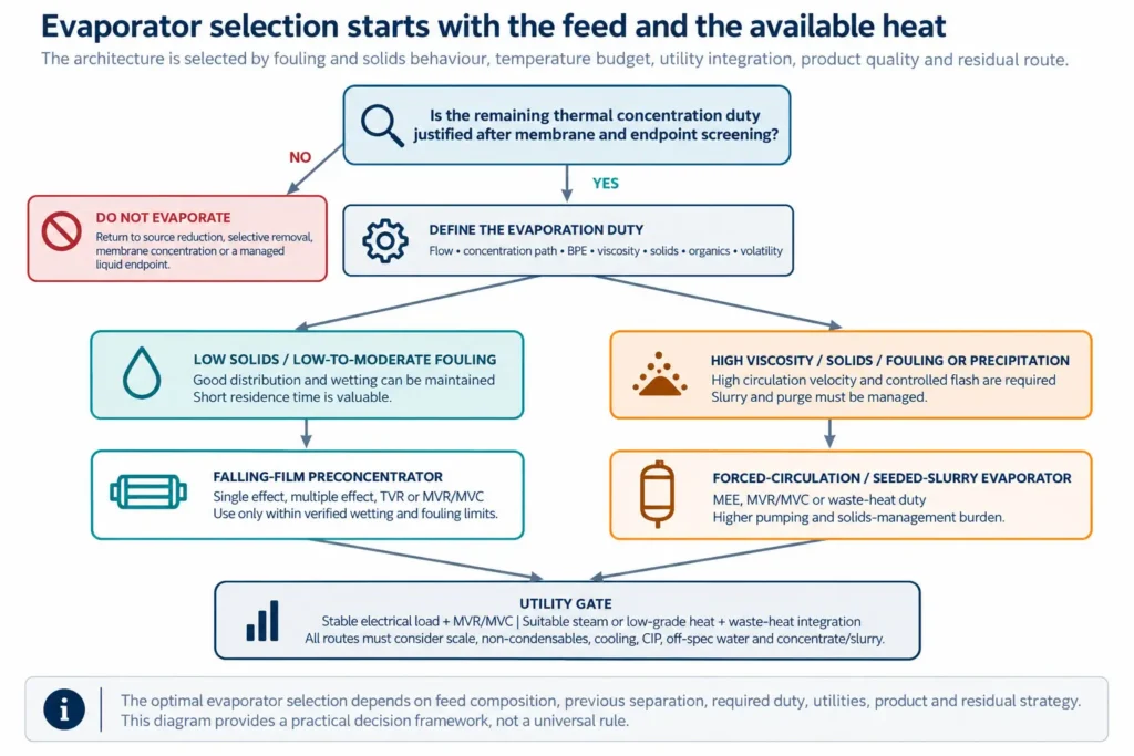
Figure 18.1. Evaporator selection logic: feed behaviour and utility integration are separate gates.
18.2 Keep heat-reuse architecture separate from evaporator hydraulics
Mechanical vapour recompression (MVR) or mechanical vapour compression (MVC) uses electrical work to raise the pressure and condensation temperature of process vapour so that its latent heat can be reused. Multiple-effect evaporation passes vapour from one effect to heat a lower-pressure effect. Thermal vapour recompression entrains part of the process vapour with motive steam. A single evaporator plant may combine these approaches with falling-film or forced-circulation bodies.
This distinction prevents a common design error: comparing an MVR plant with a forced-circulation plant as though one were an energy system and the other a competing energy system. Forced circulation can be heated by live steam, multiple effects, TVR, MVR or available waste heat. Falling film can be configured in the same ways, subject to wetting and fouling constraints.
| Architecture | Energy principle | Best fit | Primary limitation | New auxiliary streams | Decision evidence |
|---|---|---|---|---|---|
| Single-effect steam | Live steam condenses once to evaporate water. | Small duty, cheap/available steam, high flexibility or batch service. | High external thermal demand and cooling/condensate load. | Steam condensate, process condensate, vents and cooling duty. | Steam balance, temperature approach, condensate use and downside energy price. |
| Multiple-effect evaporation (MEE) | Vapour from one effect heats the next at lower pressure. | Continuous duty with sufficient total temperature difference and suitable effect allocation. | BPE, heat-transfer approach, vacuum and fouling consume the temperature budget. | Condensate by effect, non-condensables, vacuum load and inter-effect drains. | Full effect-by-effect heat/mass balance and off-design turndown. |
| Thermal vapour recompression (TVR) | Motive steam entrains and recompresses part of the process vapour. | Steam-integrated sites where motive-steam pressure and economics are favourable. | Motive-steam dependency, compression ratio and reduced flexibility. | Motive-steam condensate, excess vapour and cooling duty. | Ejector performance across pressure, BPE and operating range. |
| MVR / MVC | A compressor raises process-vapour pressure and temperature for heat reuse. | Large, stable evaporation duty with reliable electricity and maintainable compressor service. | Compressor lift, discharge temperature, non-condensables, fouling and rotating-equipment availability. | Compressor seal/oil systems, startup steam, vents, condensate and off-spec inventory. | Compressor map, energy denominator, redundancy, startup and trip-recovery plan. |
| Waste-heat heated | A matched external hot stream supplies part or all of the evaporation duty. | Co-located, reliable heat with compatible temperature, duration and control. | Temperature mismatch, intermittency, fouling on both sides and lost host-plant flexibility. | Return heat stream, backup utility, cooling and bypass. | Pinch/heat-integration study plus correlated operating schedules. |
Table 18.1. Heat-reuse architectures must be compared on the same evaporation, availability and utility boundary.
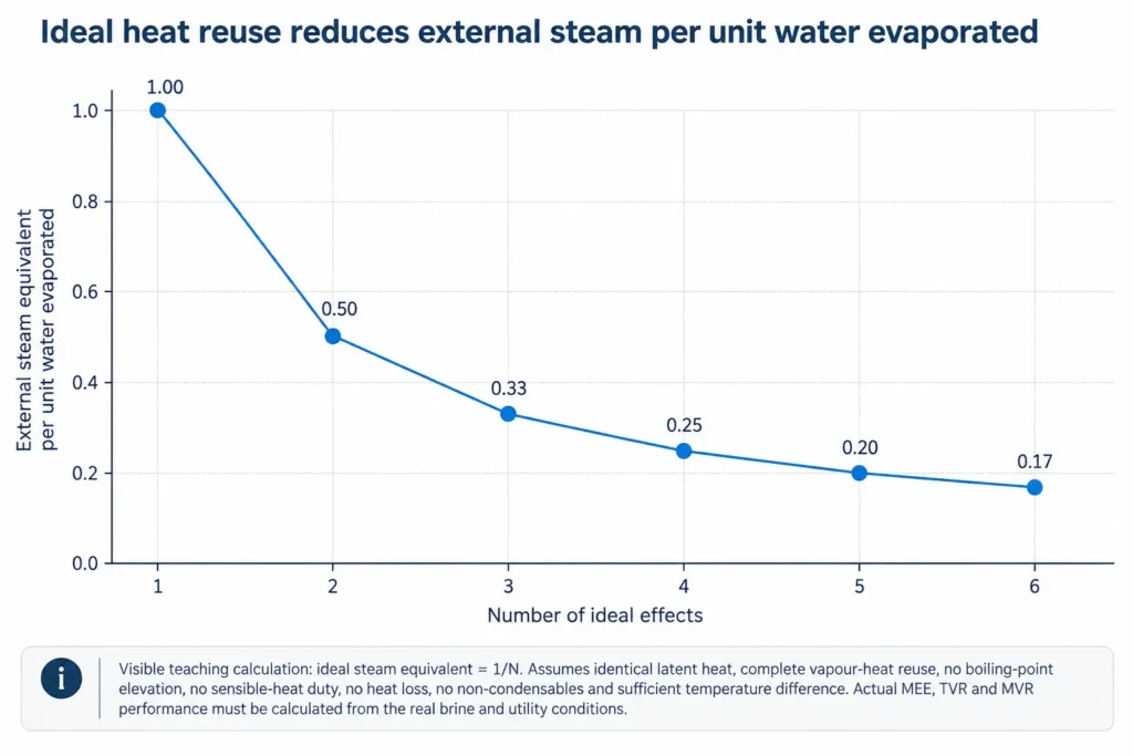
Figure 18.2. Ideal heat-reuse teaching curve. Real systems lose duty to BPE, approaches, sensible heat, fouling and auxiliary loads.
18.3 MVC and MVR brine concentrators
MVR/MVC brine concentrators are widely used because they recover the latent heat of the generated vapour rather than rejecting it after one use. GEA describes MVR as compressing process vapour to the pressure and temperature needed for reuse as heating steam, with condensate heat often recovered for feed preheating. Veolia and Aquatech publish current and historical full-scale ZLD examples using MVR/MVC falling-film brine concentrators before crystallization. These are evidence that the architecture is established—not generic guarantees for a new feed.
The compressor does not create the full latent heat of evaporation; it supplies the work needed to raise the vapour to a useful condensation temperature. The required lift grows when BPE rises, the heat exchanger fouls, the selected approach temperature is large, non-condensables accumulate or the evaporator pressure changes. Compressor power must therefore be calculated across the actual concentration path and not from feed salinity alone.
MVR systems also require a credible startup, trip and turndown philosophy. A compressor trip can stop both heat supply and water removal immediately, while the hot concentrated inventory continues to react and precipitate. Startup steam, emergency cooling, inventory storage, controlled dilution, recirculation and off-spec condensate diversion belong in the base design.
| MVR/MVC design field | Required input | Normal design question | Upset question | Acceptance evidence |
|---|---|---|---|---|
| Compressor lift | Vapour pressure, target condensing temperature, BPE and exchanger approach. | Does the compressor map cover the full concentration and ambient range? | What happens at high BPE, fouling or non-condensable accumulation? | Vendor curve plus independent process heat balance at normal/design/upset cases. |
| Vapour quality | Droplet loading, demister performance, volatile species and non-condensables. | Is clean dry vapour delivered to the compressor? | Can foam or flashing overload separation during events? | Separator/demister test basis and condensate-quality monitoring. |
| Electrical system | Power, voltage, starting current, harmonic/control needs and grid reliability. | Can the site supply stable continuous power? | How is a grid dip or trip recovered without losing inventory control? | Electrical study, backup philosophy and restart sequence. |
| Startup and turndown | Minimum stable load, startup steam/heat, recirculation and storage. | Can the unit operate through realistic production variability? | Where does feed go when the unit is unavailable? | Dynamic operating narrative and storage/alternative route. |
| Compressor availability | Redundancy, service intervals, spares, seals, lubricant and maintenance access. | Does expected availability support the site water balance? | How long can the plant remain down before upstream production is affected? | RAM study, critical-spares plan and capacity contingency. |
Table 18.2. MVR/MVC acceptance fields: compressor duty must be tied to the brine and the site operating system.
18.4 Multiple-effect evaporation and steam integration
Multiple-effect evaporation reduces live-steam use by reusing the vapour produced in one effect as the heating medium for the next. Official GEA and Alfa Laval material presents multiple effects, TVR and MVR as alternative or combined ways to reduce external steam consumption. The ideal 1/N relationship in Figure 18.2 is useful only as an upper-bound teaching concept.
The real number of effects is constrained by the total temperature difference available between the heating utility and the final condensing pressure. Every effect requires a heat-transfer approach. BPE consumes part of the available difference. Fouling requires margin. Vacuum-system and hydraulic stability create further limits. Adding effects can reduce steam demand while increasing surface area, vacuum complexity, inter-effect control and sensitivity to fouling.
A site with low-cost or surplus steam may rationally choose fewer effects or a steam-driven arrangement rather than an electrically driven compressor. Aquatech reports a bounded power-plant case in which a two-effect evaporator was selected because excess low-cost steam was available. The case demonstrates utility-driven selection; it does not establish a universal cost preference.
| MEE question | Why it matters | Required calculation | Failure if omitted | Decision output |
|---|---|---|---|---|
| How much total temperature difference is available? | Sets the gross budget for effects, approaches and BPE. | Utility temperature/pressure to final condenser pressure across all cases. | An effect train that cannot transfer design duty at high concentration. | Feasible effect count and pressure profile. |
| How is feed arranged? | Forward, backward, parallel or mixed feed changes pumping, viscosity and temperature exposure. | Effect-by-effect flow, concentration, viscosity, temperature and pump duty. | High-viscosity liquor in the wrong effect or unstable flashing. | Feed arrangement and recirculation basis. |
| Where is condensate recovered? | Condensate temperature and contamination vary by effect and service. | Separate clean/conditional/off-spec condensate balances. | Mixing contaminated condensate with reusable water. | Condensate segregation and reuse map. |
| How is turndown controlled? | Heat transfer, wetting, flashing and vacuum can change nonlinearly. | Minimum-load heat/mass balance and control narrative. | Dryout, unstable levels, compressor/ejector mismatch or carryover. | Stable operating envelope and bypass/recirculation logic. |
| What is the optimum—not maximum—effect count? | More effects trade energy against area, complexity and availability. | Lifecycle cost and downtime sensitivity with the same duty and availability. | Selecting by steam economy alone. | Risk-adjusted effect count and utility architecture. |
Table 18.3. Multiple-effect design is a temperature-budget and lifecycle-cost problem.
18.5 Falling film versus forced circulation
Falling-film evaporators distribute liquid as a thin film over heat-transfer surfaces. GEA describes them as well suited to liquids with small amounts of solids and low-to-moderate incrustation tendency, with short residence time and compatibility with multiple effects or vapour recompression. The distributor and minimum wetting rate are critical: incomplete wetting creates dry areas, local concentration and deposits.
Forced-circulation evaporators use a pump to maintain high circulation through an external heat exchanger and flash the heated liquid in a separator. GEA identifies them for highly viscous liquids, fouling tendency and high-concentration service. Veolia’s industrial vacuum evaporator descriptions likewise use forced circulation where fouling and scaling must be controlled. The price is recirculation power, larger pumps, erosion risk and a circulating solids inventory.
The selection can change along the train. A relatively clean feed may be preconcentrated in a falling-film body, then transferred to a forced-circulation or seeded-slurry unit as viscosity and precipitation risk rise. The transition point should follow verified heat-transfer, wetting and solids behaviour—not a universal TDS threshold.
| Criterion | Falling film | Forced circulation | Required test/data | Main residual/auxiliary | Failure mode |
|---|---|---|---|---|---|
| Suspended solids / crystallization | Best when low and stable; avoid uncontrolled solids deposition. | Can maintain slurry circulation and separate flash from heat transfer. | Particle size/load, induction behaviour, slurry rheology and erosion. | Purge/slurry, separator solids and cleaning waste. | Tube blockage, erosion, separator overload or uncontrolled nucleation. |
| Viscosity | Film distribution and heat transfer deteriorate as viscosity rises. | High velocity can preserve transfer, with larger pumping duty. | Viscosity versus temperature and concentration, including non-Newtonian behaviour. | Recirculation energy and pump maintenance. | Film dryout or excessive pump/heat-exchanger duty. |
| Residence time | Short; useful where heat exposure or degradation matters. | Longer circulating inventory and broader residence-time distribution. | Reaction/degradation and precipitation kinetics. | Larger hot inventory and off-spec material on trip. | Product degradation or uncontrolled chemistry during downtime. |
| Fouling / scaling | Acceptable only within verified distribution, cleaning and deposition limits. | Chosen when high velocity and external exchanger improve manageability. | Deposit tests, cleanability, online/offline cleaning and surface material. | CIP, wash, removed deposit and lost production. | Rapid U-value decline or irreversible deposit. |
| Turndown | Minimum wetting and distribution can set a hard lower load. | Recirculation can decouple tube velocity from net feed to a degree. | Minimum-load hydraulic and heat-transfer testing. | Recycle/inventory and additional pump energy. | Dry patches, level instability or flash/separator carryover. |
Table 18.4. Falling-film and forced-circulation selection must follow the concentration path, not the feed alone.
18.6 Boiling-point elevation and heat-transfer deterioration
Boiling-point elevation (BPE) is the difference between the boiling temperature of the solution and pure water at the same pressure. It reduces the usable temperature difference for heat transfer. High-salinity BPE cannot be estimated safely by extrapolating low-salinity seawater correlations. Abdelkareem and co-authors measured seawater BPE across 20–280 g/kg and 20–80 °C and reported large divergence among extrapolated correlations at high concentration. The values are specific to their seawater matrix, not a universal industrial-brine model.
A 2025 high-recovery MED analysis found that neglecting BPE can materially distort performance and economic predictions in MED-MVC configurations. The transferable conclusion is not its numerical error for every plant; it is that high-recovery effect and compressor calculations require a validated concentrated-solution property basis.
Heat-transfer deterioration is broader than BPE. Viscosity reduces liquid-side heat transfer and increases pumping. Deposits add thermal resistance. Gas and non-condensables impair condensation. Poor distribution creates dry areas. Slurry changes flow regime and erosion. The design U-value should therefore be a concentration- and time-dependent operating variable, with clean and fouled cases and a verified cleaning recovery.
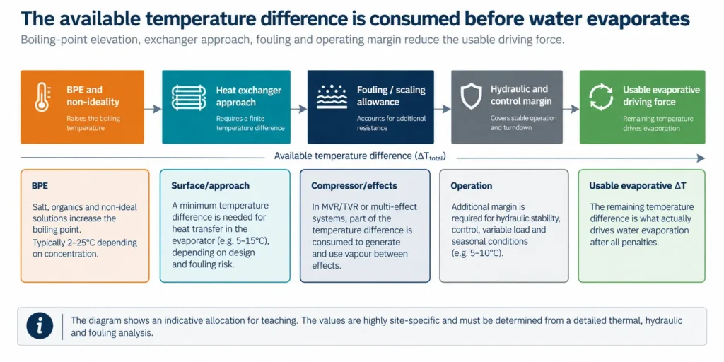
Figure 18.3. Conceptual thermal temperature budget. Segment widths are editorial, not design values.
| Thermal property / effect | Minimum basis | Design use | Cross-check | Unsafe shortcut |
|---|---|---|---|---|
| Boiling-point elevation | Measured or validated model for the actual composition, concentration and temperature. | Effect allocation, compressor lift, boiling temperature and surface area. | Bench evaporation and independent property model. | Using seawater BPE or one salt correlation for mixed industrial brine. |
| Specific heat and sensible duty | Concentration- and temperature-dependent heat capacity plus feed/return temperatures. | Preheater and startup duty, utility integration and transient response. | Energy balance and measured heat-up test. | Reporting only latent evaporation duty. |
| Viscosity / rheology | Temperature and concentration path, including slurry/non-Newtonian behaviour. | Film wetting, tube velocity, pump duty and heat-transfer coefficient. | Representative hot rheology and pilot hydraulics. | Room-temperature feed viscosity as the design value. |
| Density and vapour-liquid equilibrium | Concentrated-solution density, gas/volatile components and phase equilibrium. | Mass/volume conversion, separator sizing, flashing and condensate quality. | Sample density, vapour/condensate analyses and model closure. | Assuming all vapour is pure water. |
| Clean/fouled U-value | Surface, geometry, velocity, deposit history and cleaning recovery. | Installed area, run length and cleaning frequency. | Pilot or comparable full-scale trend with autopsy. | One clean-water heat-transfer coefficient. |
Table 18.5. Property package required before a thermal duty or surface area is credible.
18.7 Scaling, foaming and entrainment
Chapter 8 separated supersaturation from deposition. Thermal concentration intensifies that distinction because nucleation may occur in bulk liquid, on heat-transfer surfaces, at dry patches or during flashing. Seeded-slurry designs can intentionally move crystallization away from the surface, but only when seed inventory, circulation, phase identity and purge are controlled.
Foam and droplet entrainment threaten vapour compressors, condensers and product-water quality. Fine solids, oil, surfactants, organics, biological material and antifoams can become more concentrated as water is removed. Aquatech reports full-scale brine concentrators fitted with external mist eliminators, and Veolia’s current ZLD systems explicitly combine brine concentrators and crystallizers. These cases support the need for maintainable vapour separation—not a universal separator design.
A 2026 experimental study of flashing feeds showed that liquid velocity, superheat and orifice geometry can materially change droplet entrainment. Although the tested geometry and fluid do not define a brine-concentrator limit, the work reinforces that flashing and separation must be designed together.
| Mechanism | Leading indicators | Primary control | Verification | Residual / downside |
|---|---|---|---|---|
| Heat-transfer scale | U-value decline, wall temperature, pressure/temperature shift and deposit chemistry. | Selective pretreatment, seeding, velocity, surface temperature and controlled cleaning. | Pilot trend, deposit autopsy and post-clean recovery. | CIP waste, removed solids, surface damage and downtime. |
| Bulk precipitation / slurry | Turbidity/solids, particle-size trend, supersaturation and separator inventory. | Seed inventory, residence time, circulation, purge and solids classification. | Slurry tests, mineralogy and steady-state mass balance. | Purge/sludge, erosion, plugging and mother-liquor loss. |
| Foaming | Foam level, separator differential, unstable level and antifoam demand. | Source removal, hydraulic margin, compatible antifoam and foam detection. | Hot concentration/boiling test across events. | Antifoam carryover, off-spec condensate and reduced vessel capacity. |
| Droplet entrainment | Condensate conductivity/TOC, mist loading and compressor or condenser contamination. | Disengagement, demister, wash section, velocity and flashing control. | Carryover test and condensate fingerprint. | Contaminated condensate, corrosion, compressor damage and reprocessing. |
| Non-condensables | Vacuum instability, condenser approach and compressor performance drift. | Deaeration, venting, leak control and condenser/vacuum capacity. | Gas balance and leak/vent tests. | Lost heat transfer, vent emissions and higher energy. |
Table 18.6. Scaling, foaming and entrainment controls must protect both heat transfer and product water.
18.8 Vapour, condensate and volatile carryover
Evaporator condensate is recovered water only after it meets a defined specification. It can contain entrained droplets, ammonia, carbon dioxide, volatile organic compounds, low-molecular-weight acids, sulfide or other species that partition to the vapour. The vapour path can also contain non-condensable gases and aerosols. Condensate quality should therefore be predicted from source chemistry and measured separately during startup, normal operation, cleaning recovery and upset conditions.
A clean conductivity reading is not a complete condensate-quality test. Conductivity detects ionic carryover but can miss neutral volatile organics. TOC, COD or targeted organic analysis, pH, ammonia, silica, metals, oil and microbiological parameters may be needed depending on the intended reuse. Vapour washing, demisters, partial condensation, stripping or downstream polishing can protect the product, but each creates a new liquid, gas or media residual.
Condensate should be segregated by confidence state. Normal verified condensate can be reused. Startup and post-CIP condensate may require diversion. An online conductivity or TOC alarm can trigger quarantine, but the tankage and route must exist physically. The claimed water recovery should exclude condensate that is recycled internally, quarantined, lost in vents or rejected as off-spec.
| Vapour/condensate field | Source mechanism | Monitoring | Control | Destination | Claim boundary |
|---|---|---|---|---|---|
| Droplet salts / solids | Mechanical entrainment, foam, flashing and demister overload. | Conductivity, major ions, turbidity and targeted metals/silica. | Separator velocity, demister/wash and event control. | Reuse, reprocess or divert. | Count only verified product condensate. |
| Volatile organics | Partitioning or thermal transformation from feed/CIP chemistry. | TOC/COD plus targeted VOC/SVOC or product-specific tests. | Source treatment, staged condensation, stripping or polishing. | Reuse with specification, separate treatment or vent control. | Do not infer from conductivity. |
| Ammonia / acid gases | pH- and temperature-dependent volatilization. | Ammonia, pH, alkalinity/acidity and gas monitoring. | pH control, stripping/absorption and condensate polishing. | Process reuse, treatment or controlled gas route. | Include scrubber or treatment residuals. |
| Non-condensables | Air leaks, dissolved gases and reaction gases. | Vacuum load, gas composition and condenser approach. | Deaeration, tightness, vents and vacuum capacity. | Safe vent, scrubber or recovery. | Include vent emissions and utility load. |
| Startup / CIP condensate | Unstable inventory, cleaning chemicals and displaced contaminants. | Recipe/event-based testing and diversion interlock. | Dedicated tank, flush criterion and verified return to service. | Reprocess, neutralize or dispose. | Exclude until acceptance criteria are met. |
Table 18.7. Condensate is a product stream only after vapour-path contaminants and operating states are controlled.
18.9 Waste heat and utility integration
DOE defines industrial waste heat as energy lost in hot exhaust gases, cooling water, equipment surfaces and heated products, and notes that commercial recovery technologies are available but constrained by material, maintenance and other barriers. Availability alone does not make waste heat suitable for evaporation. Temperature, duty, duration, cleanliness, distance, pressure and host-process priority must match the evaporator.
The heat-integration study should use simultaneous operating data, not annual average energy. A batch wastewater stream cannot depend on waste heat that exists only during a different production campaign unless storage closes the mismatch. Likewise, using cooling water or exhaust heat can impose pressure drop, corrosion, fouling or operational risk on the host process. The avoided fuel or steam credit must be net of backup utility, heat-exchanger area, pumping, cleaning and lost flexibility.
MVR can also act as an electrically driven heat pump and may be attractive where low-carbon electricity is reliable. The comparison must keep electrical and thermal energy separate and report the denominator: per cubic metre of feed, distillate or water removed. Carbon benefit follows the actual marginal electricity, steam or waste-heat baseline—not the technology label.
| Utility option | Required site data | Integration risk | Backup / contingency | Economic and carbon basis |
|---|---|---|---|---|
| Grid electricity for MVR | Hourly/seasonal availability, tariff, demand charges, carbon factor and power quality. | Trip, peak-price exposure and compressor maintenance. | Startup steam, storage, alternative route and restart plan. | kWh per water removed plus demand, downtime and replacement. |
| Live steam / MEE / TVR | Pressure, temperature, condensate return, marginal cost and host-plant constraints. | Steam scarcity, motive-pressure variation and boiler/condensate impacts. | Alternate steam, reduced load or residual storage. | Marginal steam—not average site steam—plus condensate credit. |
| Waste heat | Source/return temperatures, flow, simultaneity, cleanliness and host priority. | Temperature mismatch, fouling, pressure drop and production conflict. | Backup heat or defined shutdown/endpoint route. | Only the reliably recoverable fraction earns credit. |
| Cooling and vacuum utilities | Ambient design, cooling temperature, water availability and vacuum load. | Hot-season loss of condensing capacity and non-condensables. | Oversize/alternate cooling, load shedding and vent control. | Include pumps, cooling tower/chiller, chemicals and water. |
Table 18.8. Thermal utilities are site systems, not equipment nameplate inputs.
18.10 Materials, cleaning and maintainability
Material selection must cover concentrated liquid, vapour, condensate, non-condensable gases, cleaning chemicals and deposits at the hottest local metal temperature. Chloride concentration alone is insufficient. Temperature, pH, oxidants, sulfide, ammonia, crevices, welds, residual stress, galvanic couples and under-deposit chemistry can govern localized attack.
Evaporator design should make deposits observable and removable. Access to distributors, tubes, separators and demisters; removable bundles or clean-in-place circuits; drainability; sampling; inspection ports; lifting space and isolation determine whether the theoretical cleaning plan can be executed. A cleanability claim should be demonstrated by recovery of heat transfer and hydraulic performance over representative cycles.
Cleaning waste can contain acids, alkalis, chelants, surfactants, dissolved metals, scale minerals, oil and high salt. It should be segregated where mixing creates gas, heat, precipitation or hazardous classification. Cleaning duration and recovery belong in the availability calculation, while chemical disposal belongs in OPEX and the endpoint register.
| Design area | Minimum question | Evidence | Operational provision | Failure consequence |
|---|---|---|---|---|
| Liquid-side materials | Can the alloy/lining withstand the full hot chemistry, deposits, erosion and cleaning? | Material review, comparable service and targeted corrosion/erosion tests. | Coupons/probes where useful, inspection and replaceable wear parts. | Localized corrosion, leakage, contamination or catastrophic downtime. |
| Vapour/condensate materials | What volatiles, droplets and gases contact compressor, condenser and piping? | Vapour/condensate analysis and upset envelope. | Demister access, drains, venting and condensate segregation. | Compressor/condenser corrosion and off-spec water. |
| CIP effectiveness | Does the sequence remove the actual deposit without damaging equipment? | Deposit-specific bench test and representative pilot cycles. | Chemical storage, heating, recirculation, neutralization and waste tanks. | Incomplete recovery, shortened life or incompatible waste. |
| Mechanical access | Can critical surfaces and separators be inspected and cleaned safely? | Maintainability review and 3D access/lifting study. | Isolation, bypass, removable internals and spares. | Excess outage duration or unsafe maintenance. |
| Fouling allowance / run length | How does performance decay between cleanings? | Time-series pilot or comparable full-scale normalized data. | Trigger limits, online cleaning or planned outage. | Installed area and availability fail the business case. |
Table 18.9. Materials and cleaning must be designed for the hottest, dirtiest and least accessible condition.
18.11 Close the thermal stream and operating ledger
A thermal block produces more than distillate and concentrate. The ledger must include feed preheat, process vapour, heating steam or recompressed vapour, clean and conditional condensate, non-condensable vents, concentrate or slurry, purge, antifoam, chemical additions, cooling-water or cooling-energy duty, CIP solutions, displaced inventory, drains, leaks and off-spec water.
The energy balance must close separately for electricity and heat. The water balance must distinguish water evaporated from water accepted as reusable distillate. The salt balance must identify entrainment, precipitation and deposit inventory. The availability basis must include startup, shutdown, CIP, compressor or vacuum-system maintenance and the route used while the unit is unavailable.
| Stream / obligation | Normal basis | Design / upset basis | Quality / composition | Destination | Cost / risk field |
|---|---|---|---|---|---|
| Product condensate | Accepted flow and temperature. | Startup/CIP diversion and carryover event. | Reuse specification and online/lab verification. | Named internal use or polishing. | Value, polishing, storage and rejection. |
| Conditional/off-spec condensate | Expected transient volume. | Maximum trip/event inventory. | Salt/TOC/ammonia/target contaminants. | Reprocess, treatment or disposal. | Tankage, lost recovery and liability. |
| Concentrate / slurry | Flow, density, solids and dissolved composition. | Maximum concentration/solids and trip hold time. | Phase identity, viscosity, corrosion and next-unit feed. | Chapter 19 crystallizer or managed MLD endpoint. | Pumping, storage, heat loss and residual route. |
| Vents / non-condensables | Gas flow and composition. | Maximum leak/reaction/upset load. | VOC, ammonia, sulfide, CO₂ and aerosol. | Safe vent, scrubber or recovery. | Emissions, corrosion and vacuum duty. |
| CIP and wash streams | Recipe, frequency and volume. | Failed clean or emergency flush. | Chemical plus dissolved deposit inventory. | Segregate, neutralize, reprocess or dispose. | Chemicals, downtime and waste acceptance. |
| Utilities and cooling | Electricity, steam, heat return, cooling and vacuum. | Peak ambient, fouled duty and restart. | Temperature/pressure/quality by interface. | Site utility system. | Demand, carbon, reliability and opportunity cost. |
Table 18.10. Thermal stream and operating ledger required before crystallizer sizing.
Thermal acceptance gateThe thermal block may advance only when its evaporation duty is justified against non-thermal alternatives; the heat-reuse and hydraulic architectures are selected separately; BPE, viscosity, heat transfer and fouling are modelled across the concentration path; vapour and condensate quality are controlled; utilities and materials are integrated with the site; and every concentrate, vent, CIP and off-spec stream has a route. |
|---|
18.12 Handover to Chapter 19
Chapter 19 separates final water removal from controlled crystallization. The handover from Chapter 18 is not merely a concentrate TDS. It is a hot or cooled feed with flow, density, temperature, dissolved and suspended composition, saturation and solids history, viscosity, antifoam and other additives, volatile contaminants, heat content, expected variability and the available mother-liquor or purge route.
The thermal concentrator should also state what it has already precipitated or retained on surfaces, which impurities remain dissolved, how much distillate is accepted as product, what condensate requires reprocessing, and how the unit behaves during trip and cleaning. Those conditions determine whether Chapter 19 can produce a controlled crystal, a mixed disposal salt, a wet sludge or only a managed final liquid.
18.13 Chapter conclusion
Thermal concentration remains important because phase-change separation can continue where membrane or electrochemical driving forces become impractical, but that reach carries a high system burden. The correct objective is to minimize the justified thermal load, not to make it disappear from the analysis.
MVR/MVC, TVR, multiple effects and waste heat are heat-reuse choices. Falling film and forced circulation are hydraulic and heat-transfer choices. Their selection must close the real temperature budget, including boiling-point elevation, exchanger approach, fouling, viscosity, non-condensables and operating margin. A clean feed can use falling-film preconcentration; a viscous, fouling or precipitating stream may require forced circulation and deliberate slurry control.
The product is not simply “distillate.” Recovered water must pass a specification that accounts for droplets, volatiles and operating state. The residual system includes concentrate or slurry, vents, condensate rejects, antifoam, cooling, compressor or steam duty, CIP and off-spec inventory. Chapter 19 now determines how the remaining liquid becomes controlled crystals, mixed salts, wet sludge or another final residual.
Chapter 18 in one sentenceThermal concentration is justified only after its duty is minimized, and it is credible only when heat reuse, temperature driving force, surfaces, vapour quality, utilities and every residual close as one operating system. |
|---|