
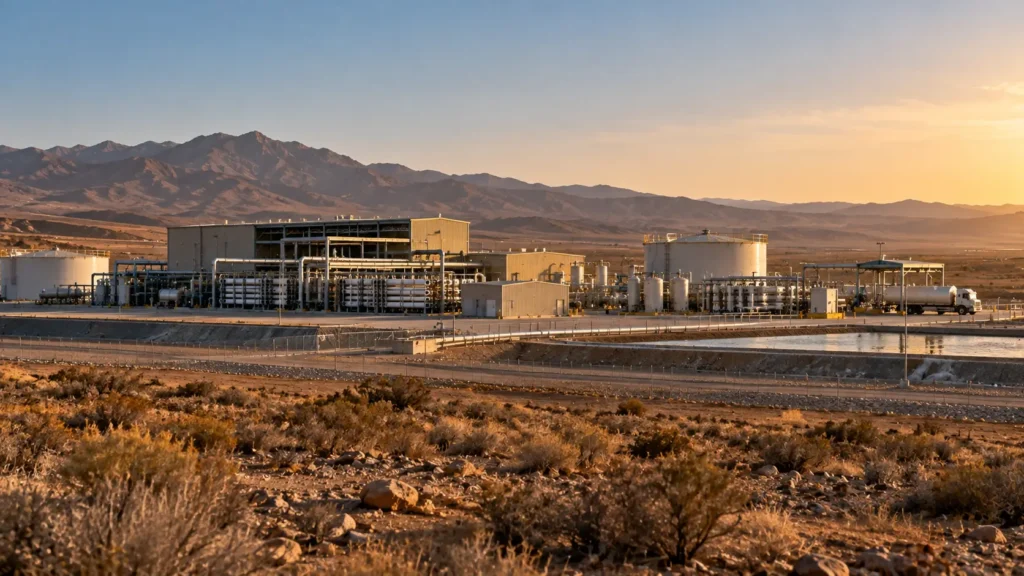
Disposal endpoint and limiting chemistry determine whether further recovery is worth the burden.
Controlled principleInland desalination and water-reuse projects should be designed from the receiving endpoint backward. The correct strategy minimizes total system burden by combining source reduction, stable primary recovery, selective removal of the chemistry that limits the next step, and a finite residual route. ZLD is one possible endpoint, not the starting assumption. |
|---|
Inland desalination is often a concentrate-management project disguised as a water-supply project
Brackish-water RO and advanced water-reuse systems create valuable product water, but inland sites may lack the simple marine discharge route available to many coastal plants. Reclamation therefore treats concentrate management as a project-specific planning problem that can include disposal, beneficial use and high-recovery processing rather than a single preferred technology.
The first design question is consequently not “how high can recovery go?” but “what liquid or solid endpoint can the site actually support?” A permitted sewer or surface-water receiver, a suitable injection formation, an evaporation or passive-management site, an off-site receiver, or a thermal ZLD endpoint creates a different process boundary. The value of additional recovered water must be compared with the extra pretreatment, energy, solids, storage, reliability and permitting burden needed to reach that endpoint.
| Design-basis field | What must be defined | Why it controls the project | Failure signal |
|---|---|---|---|
| Concentrate source | BWRO, reuse RO, industrial reuse RO or other membrane reject; normal/design/upset flow | Sets chemistry, contaminant and hydraulic boundary | Different concentrates are merged because both are “RO reject” |
| Recovered-water value | Named internal or municipal use, quality target and marginal supply value | Determines value of extracting additional water | Recovery target exists without a receiving use |
| Current residual route | Permit, capacity, receiver, distance, geology/land and backup | Defines the counterfactual and avoided cost | ZLD is selected before the baseline route is priced |
| Limiting chemistry | Hardness, sulfate, silica, alkalinity, metals, organics/CECs and additives as relevant | Determines what prevents further concentration | TDS alone is used to set high-recovery feasibility |
| Operating envelope | Seasonal flow, source switching, membrane cleaning, outages and peak salinity | Controls storage and installed capacity | Annual average hides peak concentrate duty |
| Residual form after treatment | Liquid, sludge, cake, crystals, purge, cleaning waste and off-spec inventory | Tests whether treatment creates a manageable endpoint | Liquid volume falls but a new unmanaged solid route appears |
Table 41.1. Inland concentrate planning starts with a source, water value and finite endpoint – not a recovery target.
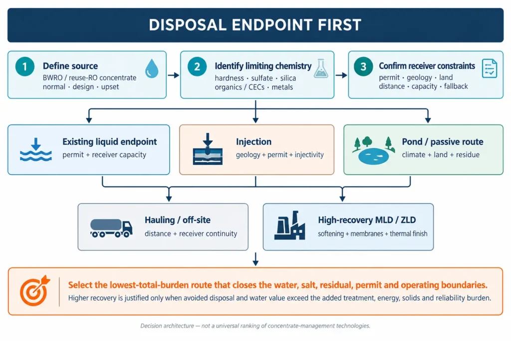
Figure 41.1. Inland concentrate endpoint comparison. The figure is a decision architecture: no endpoint is universally preferred, and every route remains conditional on chemistry, permitting, site constraints and operability.
Characterize concentrate as a new feed – not as “feedwater multiplied by recovery”
Concentrate contains the species rejected by the primary separation and may also contain antiscalants, acids/bases, coagulant residuals, cleaning carryover and constituents introduced by upstream treatment. A design analysis should therefore measure the actual concentrate across representative operating states rather than derive every constituent from one feed analysis and a nominal concentration factor.
For municipal or industrial reuse RO, the non-salt fraction can be especially important. Reclamation research on potable-reuse concentrate highlights that membrane reject can retain contaminants of emerging concern and that concentrate-management decisions must consider those constituents as well as salinity. The lesson for this guide is broader than potable reuse: a reuse-RO concentrate is not chemically equivalent to brackish-groundwater concentrate merely because the TDS is similar.
| Concentrate field | BWRO emphasis | Reuse-RO emphasis | Design consequence |
|---|---|---|---|
| Major ions + alkalinity | Ca, Mg, Na, Cl, sulfate, bicarbonate/carbonate | Same major-ion balance plus treatment-derived salts | Scaling, osmotic pressure, softening and residual mass |
| Silica | Source geology and pretreatment history | Source water plus upstream reuse treatment | May govern membrane recovery even when hardness is controlled |
| Organics / CECs | Often source-specific and sometimes low, but must be measured | Potentially important due to wastewater origin and membrane rejection | Can constrain reuse, ponds, wetlands, discharge or thermal treatment |
| Metals / trace inorganics | Geogenic or treatment-derived | Wastewater/process-derived or treatment-derived | May determine sludge classification, disposal or permit limits |
| Process additives | Antiscalant, acid/base, coagulant, cleaners | Same plus advanced-treatment chemicals as applicable | Can alter precipitation, crystallization, toxicity and recycle |
| Variability | Well blending, seasonal demand, source switching | Upstream wastewater/reuse variability and treatment state | Requires normal/design/upset compositions and storage logic |
Table 41.2. Similar salinity does not make BWRO and reuse-RO concentrates interchangeable design feeds.
Screen the residual endpoint before adding a second concentration stage
Reclamation’s concentrate-management framework separates three broad families: disposal, beneficial use and high-recovery processing. Disposal can include routes such as sewer or surface discharge, evaporation ponds, land application or deep-well injection where legally and physically available; high-recovery processing can reduce liquid volume and create additional water, but introduces another treatment and residual-management duty.
This chapter does not convert those categories into a global ranking. Discharge and injection are permit- and jurisdiction-specific. Pond performance depends on climate, land, liner/leakage controls and residue management. Hauling depends on distance, receiver capacity and uninterrupted logistics. High-recovery membrane or thermal systems depend on chemistry, scale, materials and operator capability. The endpoint comparison must therefore be explicit before detailed process selection.
| Endpoint family | Minimum evidence before selection | Principal constraint to test | Required fallback |
|---|---|---|---|
| Permitted liquid discharge / sewer | Current permit/receiver criteria, hydraulic and salt-load capacity, monitoring | Receiving-water or treatment-plant constraints; future permit risk | Storage and alternate receiver/treatment route |
| Injection | Hydrogeology, well class/permit pathway, injectivity, compatibility, monitoring and closure basis | Suitable isolated formation and regulatory authorization | Storage plus alternate disposal/treatment route |
| Evaporation pond / passive management | Climate/water balance, land, liner/leakage, residue handling, wildlife/environmental review | Land and evaporation balance; long-term salt/solid accumulation | Overflow/extreme-weather and residue-removal route |
| Hauling / off-site receiver | Manifest/classification, receiver acceptance, distance, fleet and weather/road continuity | Recurring logistics and receiver dependence | Emergency storage and secondary receiver |
| High-recovery MLD | Pretreatment, scaling envelope, residual liquid route, energy and availability | Whether volume reduction meaningfully changes endpoint economics | Original lower-recovery route retained as downside comparison |
| Thermal ZLD | Complete water/salt balance, heat/electricity, materials, solids handling and off-spec route | Final thermal duty, solids reliability and full residual acceptance | Finite emergency storage and managed off-spec route |
Table 41.3. Every inland endpoint is conditional; a process train is defensible only when its receiver and fallback are real.
Optimize the primary RO system only inside its stable chemistry and operating envelope
Increasing primary RO recovery can reduce concentrate volume without adding a separate plant, and Reclamation includes pretreatment, RO operational improvements and membrane selection among concentrate-minimization options. But a nominal recovery increase is useful only if normalized performance, scaling risk, membrane cleaning, permeate quality and availability remain acceptable over the representative feed distribution.
The project should distinguish source reduction from forced recovery. Better well blending, upstream softening, staged operation, improved antiscalant control, repaired bypasses or corrected concentrate throttling can reduce reject or improve stability. By contrast, simply raising recovery until the scaling margin disappears can transfer cost into cleaning, replacement and unplanned downtime.
| Primary-system lever | What it can improve | Evidence required | Do not assume |
|---|---|---|---|
| Feed/source segregation or blending | Lower peak scaling or contaminant duty | Hydraulic + ion-load balance across source states | Blending always reduces risk; incompatible chemistry can worsen scaling |
| Pretreatment optimization | More stable feed quality and fouling control | Normalized RO trends, filtration/SDI or relevant fouling indicators | Better pretreatment automatically supports higher recovery |
| Stage / array / hydraulic optimization | Better use of membrane area and pressure profile | Vendor/model calculation checked against plant data | Nameplate recovery equals sustainable recovery |
| Chemical programme | Control of defined precipitation mechanisms | Speciation/scaling model plus field/pilot evidence | Antiscalant removes the need for ion-specific limits |
| Membrane selection / replacement | Potential pressure, rejection or fouling benefit | Comparable test boundary and product-water requirement | A newer membrane fixes poor concentrate chemistry |
| Cleaning and monitoring | Preserve availability at the selected operating point | Trigger limits, normalized trends, CIP waste route | Frequent cleaning is an acceptable substitute for design margin |
Table 41.4. Primary RO recovery is an operating envelope, not a single vendor or design-sheet number.
Selective softening is justified when it removes the species that blocks the next recovery step
Reclamation’s concentrate-management work identifies intermediate treatment as a way to remove or reduce scale-forming salts before secondary desalination. The cited methods include ion exchange, lime softening, pellet softening and other chemical precipitation; separate Reclamation work specifically investigated pellet softening as a concentrate-minimization step.
The governing principle is selective removal rather than indiscriminate purification. If calcium carbonate, calcium sulfate, silica or another phase limits the next membrane stage, the pretreatment should target that constraint and carry the resulting sludge, reagent ions, wash water and residual hardness into the full balance. Softening is valuable only if the downstream recovery or endpoint benefit exceeds those new burdens.
| Limiting mechanism | Possible control function | Evidence needed before scale-up | New burden to close |
|---|---|---|---|
| Carbonate hardness / alkalinity | pH control, precipitation/softening or ion exchange as justified | Speciation, kinetics, seed/sludge behavior and residual Ca/alkalinity | Sludge/cake, reagent salts, pH correction |
| Calcium sulfate / sulfate-rich scale | Selective Ca or sulfate control; staged precipitation where justified | Supersaturation behavior in actual concentrate and recycle | Sulfate/Ca-rich solids or secondary brine |
| Silica | Source control, pH/chemistry management or silica-specific pretreatment where proven | Real-concentrate pilot and cleaning behavior | Silica-rich sludge/media waste or recovery loss |
| Metals / phosphate / other specific ions | Source-specific precipitation, adsorption or ion exchange | Matrix-specific removal and downstream compatibility | Concentrated hazardous or regulated residual where applicable |
| Mixed scale + organics | Sequence solids/organic control before high recovery | Integrated test; not separate jar tests only | Multiple residuals and greater operator complexity |
Table 41.5. Selective softening should remove the constraint on the next step and explicitly account for the solids it creates.
Secondary membrane recovery is an MLD option only when the residual liquid endpoint improves
High-recovery processing can take concentrate directly or after intermediate treatment and extract additional usable water. Reclamation’s planning framework recognizes both routes and recommends desktop study and pilot testing because technology performance and cost are application-specific. The same caution applies to RO, EDR/ED, closed-circuit RO, NF hybrids or other membrane/electrochemical concentrators.
The correct metric is not second-stage recovery in isolation. The model should show overall site water recovery, residual liquid volume, ion loads, product-water quality, energy, chemicals, membrane/media replacement, cleaning losses, availability and the final receiver. A high-recovery membrane train that leaves a small but chemically unmanageable liquid residual has not solved the endpoint problem.
| Secondary-recovery question | Proceed evidence | Conditional signal | Stop signal |
|---|---|---|---|
| Feed compatibility | Real-concentrate test inside defined chemistry envelope | One bounded scale/fouling uncertainty remains | Performance depends on synthetic water or excluded routine contaminants |
| Product-water use | Named receiving duty accepts product quality | Polishing requirement is bounded | No useful destination for additional recovered water |
| Residual reduction | Materially reduces the volume/cost/risk of the final endpoint | Reduction helps but receiver capacity remains tight | Concentrate becomes harder to manage without changing endpoint cost |
| Availability / cleaning | Integrated run demonstrates stable normalized performance and recoverable cleaning | Cleaning frequency remains a bounded scale-up item | Availability requires chronic cleaning or unproven operator burden |
| Economics | Avoided disposal + water value exceed full incremental burden in downside case | Positive only after additional evidence | Case fails without optimistic energy, recovery or disposal assumptions |
Table 41.6. A secondary membrane stage is an endpoint tool, not a recovery trophy.
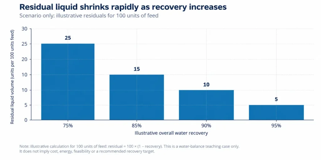
Figure 41.2. Scenario-only water balance. For a 100-unit feed, residual liquid equals 100 × (1 – recovery). The graph illustrates volume compression only; it is not a cost, energy, feasibility or recommended-recovery curve.
Reuse-RO concentrate can carry non-salt constraints that dominate the endpoint
Water reuse expands local supply value and can make additional recovery attractive. EPA’s current industrial-reuse resources emphasize fit-for-purpose use and jurisdiction-specific quality requirements rather than one universal reuse specification. The concentrate side of the same project requires equal discipline: the source wastewater, upstream treatment barriers and rejected trace constituents can govern disposal or further treatment even when ionic salinity is moderate.
For potable or high-grade reuse applications, Reclamation research has specifically examined contaminants of emerging concern in RO concentrate and their implications for ponds, wetlands and other concentrate routes. This guide therefore treats organics/CECs, nutrient species and trace contaminants as potential endpoint gates in reuse concentrate; they are not assumed to be removed merely because the next step is another salt-concentration process.
| Reuse-concentrate question | Why it matters | Evidence / control |
|---|---|---|
| What upstream wastewater created the concentrate? | Determines organics, nutrients, trace contaminants and variability | Source/reuse treatment train plus representative concentrate analyses |
| What is the additional recovered water for? | Sets polishing and reliability requirement | Named use, product-water spec and integration point |
| Which rejected constituents constrain disposal? | Salt may not be the only environmental or permit driver | Receiver-specific contaminant screen, not TDS only |
| Will further concentration increase a non-salt risk? | Higher recovery raises rejected-solute concentration and can shift phase behavior | Mass balance and treatment/endpoint testing at design concentration |
| What happens during upstream treatment upset? | Reuse feed quality can change with wastewater and advanced-treatment operation | Hold/divert logic and design/upset concentrate basis |
Table 41.7. Reuse-RO concentrate should preserve the wastewater-origin contaminant boundary as well as the salt balance.
Evaporation ponds and passive routes trade process complexity for land, climate and long-term residue obligations
Evaporation ponds are a real concentrate-management route: Reclamation’s Brackish Groundwater National Desalination Research Facility operates evaporation ponds for concentrate disposal and research. Their existence, however, should not be interpreted as a universal recommendation. Pond feasibility is fundamentally site-specific and must close the climatic water balance, liner/leakage controls, land, wildlife/environmental issues, precipitation, freeboard, storm events and the eventual salt/sludge removal route.
Passive or nature-based routes can also be evaluated where the receiving ecology and contaminants allow it, but the same mass-balance rule applies: evaporation removes water, not salt or persistent contaminants. The design must state what accumulates, at what rate, how it is monitored, and what happens when the storage or solids capacity is reached.
| Pond/passive design field | Required basis | Failure mode to avoid |
|---|---|---|
| Water balance | Monthly/seasonal inflow, evaporation, precipitation, seepage assumption, freeboard and upset inflow | Annual average shows balance but wet-season storage overflows |
| Land + civil containment | Footprint, geotechnics, liner/leak detection, access and expansion | Land requirement or seepage control is treated as “free” |
| Chemistry evolution | Precipitation sequence, density, pH, trace contaminants, scaling and odor/biological issues as relevant | Salt and contaminants accumulate without an endpoint model |
| Solids / salt removal | Removal method, dewatering, handling, classification and receiver | Pond is called disposal although solids remain indefinitely unmanaged |
| Environmental / wildlife interface | Applicable permitting, exposure pathways, bird/wildlife controls and monitoring | Concentrate toxicity is inferred from salinity alone |
| Extreme events / closure | Emergency storage, storm sequence, pond cleanout and closure liability | Routine operation has no finite end-state |
Table 41.8. Ponds reduce liquid volume only when the water balance, containment and accumulated-residual route remain controlled.
Hauling can be a strategic buffer or small-flow solution, but logistics become part of treatment reliability
Hauling moves the endpoint off site; it does not eliminate it. For small, intermittent or commissioning flows it can provide valuable flexibility, and it may remain an emergency route even after a permanent solution is built. For routine large flows, however, truck frequency, receiver hours, weather, road access, classification, manifesting, loading/unloading and receiver continuity can become dominant system constraints.
The economic model should therefore separate temporary/fallback hauling from a permanent baseline. A low treatment CAPEX can be offset by recurring transport and receiver cost, while a highly reliable off-site receiver may still be preferable to complex on-site ZLD at some sites. The comparison belongs in total delivered cost and service risk, not in technology ideology.
| Hauling field | Base-case record | Downside test |
|---|---|---|
| Daily / peak residual volume | Normal and peak loads with density/payload basis | Peak production + one missed collection window |
| Receiver | Named permitted receiver, quality acceptance and daily capacity | Primary receiver unavailable |
| Transport | Distance, cycle time, payload, fleet and loading interface | Road/weather restriction or carrier shortage |
| Storage | On-site buffer sized to credible interruption | Maximum plausible receiver outage |
| Cost basis | Transport + receiver + loading + testing + storage + administration | Fuel/freight escalation and lower payload |
| Fallback | Secondary receiver or temporary process turndown | No route other than indefinite storage |
Table 41.9. Hauling is an operating interface with a receiver and continuity requirement, not a zero-CAPEX disposal assumption.
Injection is a geology-and-permitting option, not a generic inland disposal sink
In the United States, EPA’s Underground Injection Control programme classifies injection wells by fluid and risk context. Class I wells are used for hazardous and non-hazardous wastes in deep confined formations, with permitting and requirements covering siting, construction, operation, monitoring, reporting and closure. Those rules are U.S.-specific, but they illustrate the broader engineering point: injection feasibility is controlled by geology, compatibility, permitting and long-term containment rather than by concentrate volume alone.
A global project should therefore avoid copying U.S. well classes into another jurisdiction. The screening package should instead identify the competent authority, candidate formation, injectivity/pressure, geochemical compatibility, pretreatment needs, monitoring and closure liability. If those are not established, “deep-well injection” remains a conceptual option rather than a bankable endpoint.
| Injection screen | Minimum evidence | Stop / recycle signal |
|---|---|---|
| Jurisdiction + permit pathway | Applicable injection/disposal law, authority and classification | No legally available pathway |
| Geologic confinement | Target formation, confining units and protected groundwater boundary | Uncertain containment or protected aquifer conflict |
| Injectivity + pressure | Test/model basis for sustainable rate and pressure | Required flow exceeds demonstrated injectivity |
| Fluid-rock compatibility | Scaling, precipitation, corrosion and plugging potential | Compatibility risk has no pretreatment/control |
| Well integrity + monitoring | Construction/materials, mechanical integrity, monitoring and reporting plan | Long-term integrity cannot be demonstrated |
| Closure + contingency | Plug/abandon basis, liability and alternate route | Project has no route during well outage |
Table 41.10. Injection is a complete subsurface disposal system with an outage and closure obligation.
MLD and ZLD configurations should be compared as conditional endpoint architectures
The inland sector does not have one “typical” train. A stable primary RO with a permitted concentrate receiver may already be the optimum. Where disposal capacity or water value justifies more recovery, the next architecture may be selective softening followed by secondary RO/EDR or another high-salinity membrane process. Where liquid discharge must be eliminated, the residual can proceed to thermal evaporation and crystallization after chemistry-specific conditioning.
Each configuration should keep the same system boundary: feed water, product water, chemical additions, sludge, secondary concentrate, evaporation, crystals/salts, mother liquor/purge, cleaning wastes, energy, downtime and the final receiver. The comparison is invalid if the ZLD case counts dry solids but the MLD case hides its remaining liquid disposal cost – or vice versa.
| Architecture | When it may fit | Critical gate | Residual endpoint |
|---|---|---|---|
| Primary RO + existing disposal | Receiver is permitted, finite and economically defensible | Permit/capacity and chemistry compatibility | Concentrate to named receiver |
| Primary RO + selective softening + secondary membrane | Further water has value and one/few scale mechanisms can be removed | Integrated softening + membrane evidence | Smaller liquid residual plus softening sludge |
| Primary RO + high-recovery membrane + pond/hauling | Residual volume reduction materially improves land/logistics burden | Residual chemistry remains acceptable to receiver | Concentrated liquid plus treatment wastes |
| Membrane MLD + evaporator | Thermal finishing justified but crystallizer can be avoided | Evaporator scaling/materials and final brine route | Small high-strength liquid + condensate + solids |
| Full ZLD: membrane/conditioning + evaporator + crystallizer | No routine liquid discharge is required and full solids route is credible | Thermal duty, crystallizer reliability, mother-liquor/purge and solids route | Solids/sludge + gases/condensate contaminants + non-routine wastes |
Table 41.11. Inland MLD/ZLD architectures are endpoint-dependent patterns, not universal recovery hierarchies.
Residual accounting determines whether higher recovery actually reduces system burden
Every additional recovery step concentrates non-volatile mass and often creates new reagent-derived solids or cleaning wastes. The residual register should therefore track dry solids and entrained water, liquid purges, membrane/CIP wastes, spent media, pond residues, off-spec product, condensate quality and any air/off-gas treatment. A project that converts one manageable brine into several difficult residuals can reduce liquid volume while increasing total burden.
Valorization remains optional upside. Inland plants may generate salts or precipitates, but the earlier product-qualification rules still apply: specification, consistency, legal status, reliable quantity, user/buyer, logistics and net value must be proven before revenue credit is used. The water-supply case must survive a no-product-revenue scenario.
| Residual stream | Mass / quality basis | Routine endpoint | Downside / off-spec endpoint |
|---|---|---|---|
| Primary / secondary concentrate | Flow, density, ion loads, organics/trace contaminants | Permitted liquid receiver or next treatment step | Emergency storage / alternate receiver |
| Softening sludge / precipitate | Dry solids, moisture, phase/impurities, leachability/classification where relevant | Approved reuse or disposal | Managed waste route with no product revenue |
| Thermal concentrate / mother liquor | Flow, density, non-crystallizing impurities, purge rate | Crystallizer or controlled purge route | Finite storage + disposal |
| Crystals / salt | Phase, purity, moisture, on-spec fraction | Qualified user/buyer or approved disposal | Rework/downgrade/disposal |
| CIP / cleaning waste | Volume, pH, dissolved/particulate load and incompatibilities | Neutralization / compatible treatment route | Segregated temporary storage and external disposal |
| Condensate / recovered water | Quality distribution and contaminants carried over | Named reuse/product-water destination | Polishing, recycle or alternate controlled route |
Table 41.12. Higher recovery is credible only when every new liquid and solid stream has a finite routine and fallback endpoint.
Design for seasonal demand, source switching, membrane cleaning and disposal outages
Inland systems often serve water-demand peaks and drought resilience, so average annual flow can understate the conditions that matter most. Source wells may be blended differently, reuse flows may change, evaporation may be seasonal, injection or sewer receivers may be unavailable, and high-recovery equipment may require cleaning precisely when water demand is high. The operating-state model should connect source, treatment and endpoint availability.
Emergency storage should be sized from a credible interruption sequence, not a generic number of hours. The owner should know what happens when the secondary membrane is offline, a pond has insufficient freeboard, a truck receiver closes, or an injection well is unavailable. The acceptable response may be turndown, bypass to a permitted baseline, temporary storage or alternate disposal – but it must be designed rather than improvised.
| Operating state | What changes | Required control |
|---|---|---|
| High water demand | Primary plant flow and concentrate generation rise | Installed concentrate capacity or planned recovery/turndown logic |
| Source-well / feed switch | Ion balance, silica, temperature or contaminants shift | Predefined routing, chemistry trigger and operating recipe |
| Primary or secondary CIP | Product water falls; cleaning waste and restart risk rise | Storage, redundancy, segregated CIP endpoint and restart criteria |
| Disposal receiver outage | Permitted liquid outlet disappears temporarily | Emergency storage, alternate receiver or production reduction |
| Wet / low-evaporation season | Pond net evaporation falls and freeboard risk rises | Seasonal water balance and inflow control |
| Off-spec recovered water or solids | Reuse/product route unavailable | Recycle/rework or managed residual route without stopping the water obligation |
Table 41.13. Inland concentrate systems must preserve the water-service obligation through endpoint and treatment outages.
Economics should value avoided disposal and additional water before speculative product revenue
The economic counterfactual is the best credible lower-complexity route, not “do nothing” by default. For an existing BWRO plant it may be current sewer discharge, injection, pond operation or hauling; for a new project it may be a lower-recovery plant with a larger residual system. The incremental business case for higher recovery should include avoided residual volume/capacity, additional water value and any deferred infrastructure, then subtract complete pretreatment, energy, chemical, replacement, labour, residual and reliability costs.
Reclamation’s Toolbox is explicitly a planning-level screen and recommends desktop and pilot work for project-specific performance and cost estimates. That caution is especially important here because endpoint costs vary strongly by location and regulation. Generic CAPEX/OPEX or a universal “cost of concentrate disposal” should not be used as a chapter benchmark.
| Economic line item | Base-case basis | Mandatory downside |
|---|---|---|
| Additional recovered water | Marginal value of named water use; quality and availability adjusted | Lower water value or lower high-recovery availability |
| Avoided disposal capacity / cost | Volume and load actually removed from the baseline endpoint | Receiver cost lower than expected or endpoint capacity expansion still required |
| Pretreatment / softening | Installed cost + reagent + solids handling + replacement | Higher dose/sludge and lower downstream benefit |
| Secondary membrane / thermal | Installed CAPEX, energy, cleaning, replacement and labour | Higher energy, more cleaning, lower availability |
| Residuals | All routine and off-spec liquids/solids including transport/receiver | No-product-revenue and higher disposal-cost cases |
| Reliability / storage | Redundancy, emergency volume, outage consequences and support | Critical unit/receiver outage coincident with peak water demand |
Table 41.14. The business case for higher recovery is the avoided endpoint burden plus water value minus the complete incremental system burden.
Inland desalination and reuse acceptance gate
An inland MLD or ZLD concept should advance only when the source, water use, chemistry, endpoint, operating states and downside economics are auditable. Weighted scoring cannot compensate for an absent legal residual route or an unvalidated limiting chemistry.
| Gate field | Proceed | Conditional / recycle | Stop | Required record |
|---|---|---|---|---|
| Source + variability | Representative BWRO/reuse concentrate basis exists | One bounded operating state needs sampling | Design is based on one feed analysis or TDS | Sampling/design-basis register |
| Water value / product water | Named use and required quality are defined | Polishing/integration remains bounded | No useful destination for additional recovered water | Water-use and quality specification |
| Limiting chemistry | Scale/fouling/contaminant envelope is demonstrated | Pilot/model closure needed on one mechanism | Higher recovery depends on untested chemistry control | Chemistry and pretreatment register |
| Residual endpoint | Routine and fallback receiver are permitted/credible and capacity-checked | One permit/capacity item remains bounded | Endpoint is conceptual or assumes indefinite storage | Residual endpoint and capacity plan |
| Operability | Cleaning, storage, spares and receiver outages are executable | Early-life support closes a defined gap | Service depends on unavailable operator/support capability | O&M and operating-state plan |
| Economics | Avoided water/disposal value survives no-product, higher-energy and lower-availability cases | One material commercial input awaits evidence | Case closes only with optimistic product revenue or omitted residual cost | Lifecycle model and downside cases |
Table 41.15. Inland concepts advance only when water value, limiting chemistry and the residual endpoint are simultaneously controlled.
Stop ruleStop, simplify or re-stage when the project has no defined concentrate receiver; when a higher recovery target is selected before limiting chemistry is demonstrated; when ponds, hauling or injection are treated as unlimited sinks; when reuse concentrate is characterized only by TDS; or when ZLD economics require speculative salt sales. Do not pay for the final recovery increment until it changes a real water or disposal constraint. |
|---|
Handover to the red-thread case studies
The master specification places four red-thread cases after the sector playbooks: inland BWRO concentrate, mining hypersaline groundwater, produced water and chemical-industry wastewater. Chapter 41 completes the sector-specific inputs for Case A. The case should now demonstrate the full decision sequence from incomplete initial data to a selected endpoint without turning any scenario into a generic design benchmark. [BC]
For the inland case, the handover must retain the original concentrate source and variability, water-value objective, limiting chemistry, disposal counterfactual, selective-softening logic, primary and secondary recovery boundaries, residual routes, operating states and downside economics. The point of the case is to show why one site may rationally stop at MLD while another may justify thermal ZLD – not to establish a universal recovery target.
| Chapter 41 field | Case A – inland BWRO requirement | Red-thread discipline |
|---|---|---|
| Initial source / objective | Defined brackish source, RO duty, product-water use and reason to act | State missing information before choosing technology |
| Concentrate chemistry | Normal/design/upset ions, silica, additives and relevant contaminants | Chemistry distribution, not TDS only |
| Baseline endpoint | Named existing or credible disposal route with capacity and cost boundary | Counterfactual remains visible in every comparison |
| Recovery constraint | Specific scale/fouling/osmotic/receiver mechanism that limits further recovery | Selective pretreatment only where it removes that constraint |
| Option set | Lower-recovery disposal, high-recovery MLD, pond/haul/injection where credible, and ZLD if justified | Do not force every option to the same endpoint |
| Residual + operations | Sludge/concentrate/solid/CIP routes, storage, outage and fallback | Every separation creates another stream |
| Economics + recommendation | Avoided water/disposal, full incremental cost and downside cases | Final recommendation reflects evidence maturity and local endpoint |
Table 41.16. The inland red-thread case should teach endpoint-first decision discipline rather than a preferred equipment train.
Chapter conclusion
Inland desalination and water reuse make concentrate management visible as a system boundary. The best project may be a stable primary RO with a defensible liquid endpoint, a selectively softened secondary membrane train that reduces an expensive residual, a pond or off-site route suited to the site, or a thermal ZLD system where discharge is genuinely unavailable. The answer depends on local water value, limiting chemistry, land/geology/logistics, regulation and operating capability.
The sequence is therefore endpoint first, chemistry second and technology third: define the receiving route; characterize the actual concentrate; optimize stable primary recovery; selectively remove the species that blocks the next step; compare MLD and ZLD against ponds, hauling, injection or permitted discharge on the same lifecycle boundary; and keep the no-product fallback intact. Maximum recovery is useful only when it solves a real constraint.
Chapter 41 in one sentenceFor inland desalination and reuse, the bankable recovery target is the point where additional water value and avoided disposal burden still exceed the added chemistry, residual, energy and operating burden. |
|---|