

Large plants must be maintainable and predictable.
Controlled principleOperability is not a commissioning afterthought. The design is complete only when the owner can run, verify, clean, maintain, diagnose, shut down and restart the full source-to-endpoint system with defined people, data, spares, residual routes and degraded modes. |
|---|
Operability is a design output, not an O&M appendix
Chapter 34 hands operations the as-awarded process boundary, guaranteed operating envelope, operator and laboratory duties, maintenance and cleaning assumptions, spares, materials inspection, residual routes, emergency storage and support commitments. Chapter 35 converts those contractual inputs into the daily capability needed to deliver water and manage residuals when the plant is normal, degraded, under maintenance or recovering from an upset. [BC-34]
ISO 55001:2024 places stronger emphasis on operational planning, life-cycle management, data and knowledge within an asset-management system. DOE O&M guidance similarly treats operations, maintenance, engineering, training and administration as an integrated system rather than independent departments. [1,3] The practical consequence for MLD/ZLD is that a technically capable train can still be operationally weak if access, staffing, monitoring, cleaning, spares, residual capacity or recovery procedures are not designed with the process.
| O&M design field | Minimum controlled basis | Design question | Failure signal |
|---|---|---|---|
| Service and boundary | Required water/residual duty, battery limits, recycle/purge and fallback endpoints. | Can the obligation be met in normal and degraded states? | Operators depend on undocumented owner/vendor scope. |
| Operating envelope | Normal, design and upset ranges; permissives, trips, exclusions and remedies. | Are limits observable and actionable? | Routine operation sits outside the guarantee basis. |
| People and tasks | Shift roles, rounds, sampling, intervention and escalation. | Can the site execute the stated operating philosophy? | Automation or specialist assumptions exceed site capability. |
| Maintenance / cleaning | Tasks, frequency basis, access, isolation, wastes, restoration criteria. | Can work be performed safely within the availability model? | A required task needs unplanned shutdown or inaccessible equipment. |
| Support / spares | Critical spares, consumables, tools, vendor support, lead times and obsolescence. | What restores service after credible failures? | A minor failure creates a long outage. |
| Data / laboratory | Online tags, calibration, sampling, analyses, historian and raw-data rights. | Can degradation be distinguished from normal variability? | Decisions depend on unverified or unavailable data. |
| Residual / emergency | Storage, bypass/fallback, sludge/salt routing and safe shutdown/restart. | Where does every stream go during abnormal operation? | Upset management creates non-compliance or forces uncontrolled shutdown. |
Table 35.1. Operability should be designed around the service obligation, operating envelope, people, maintenance, data and failure-recovery routes.
Operator competency and task ownership must match the process
An MLD/ZLD plant combines water treatment, high-ionic-strength chemistry, rotating equipment, chemical dosing, solids handling and often thermal concentration. The competence question is therefore task-specific: who recognizes a developing constraint, who verifies it, who is authorized to intervene, and who can restore the system after the intervention? ISO 55012:2024 links asset-management outcomes to people involvement, knowledge, competence and development planning.
Do not convert every task into a generic “operator responsibility.” Distinguish routine shift work from laboratory release, maintenance isolation, specialist membrane or crystallizer work, corrosion inspection, control-system changes and vendor-supported diagnostics. Each critical task needs a primary owner, competent backup and escalation route.
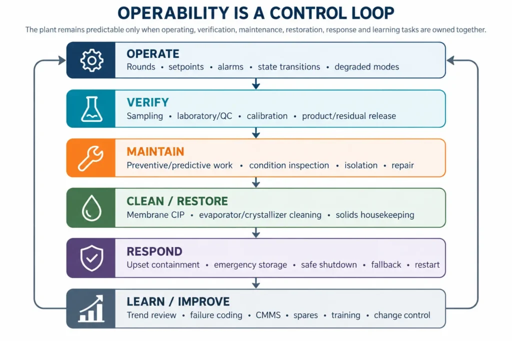
Figure 35.1. Operator task map. Operability is a coordinated loop of operating, verification, maintenance, restoration, response and learning tasks—not an automation claim.
| Task family | Minimum competence | Evidence of readiness | Backup / escalation | Failure if missing |
|---|---|---|---|---|
| Operate | Process states, chemistry limits, alarms, interlocks, chemical and solids hazards. | Task qualification, supervised runs and approved operating procedures. | Shift lead / process engineer. | Operators chase symptoms or override protective logic. |
| Verify | Sampling, field instruments, laboratory methods, calibration status and data interpretation. | Method training, QC records and proficiency checks appropriate to the site. | Laboratory lead / external accredited support. | Control decisions use biased or non-comparable results. |
| Maintain | Isolation, rotating equipment, valves, pumps, heat transfer, instrumentation and condition inspection. | Maintenance plans, permits, task history and competency records. | Specialist contractor / OEM. | Preventable failures become long outages. |
| Clean / restore | CIP or wash sequence, chemistry compatibility, waste routing and recovery check. | Approved procedure and demonstrated post-clean restoration. | Process specialist / OEM. | Cleaning damages equipment or creates a new residual problem. |
| Respond / restart | Emergency storage, safe state, preservation, restart sequence and degraded mode. | Drills, scenario walkthroughs and commissioning/start-up records. | Incident lead / engineering / vendor. | Upset response is improvised under time pressure. |
| Improve | Trend review, failure coding, change control, optimization and training updates. | CMMS/historian review and controlled lessons-learned process. | Asset/process owner. | Recurring defects become normalized. |
Table 35.2. Competency should be assigned to defined tasks, with evidence, backup and escalation—not assumed from job titles.
Automation and online monitoring should reduce ambiguity, not remove operator responsibility
Automation should make the operating envelope visible, enforce protective logic and give operators enough context to distinguish a process disturbance from an instrument problem. It should not hide a fragile process behind a single “plant healthy” indicator. ISO 55013:2024 treats data as an asset that must remain useful for asset-management objectives; ISO 55001:2024 also strengthens data and information requirements.
The tag list should follow the failure modes and decisions. Where a variable controls a guarantee, permit, product release or maintenance trigger, define the measurement range, accuracy need, redundancy or cross-check, calibration basis, bad-data behavior, alarm logic, historian retention and owner of the resulting action. More sensors are not automatically better; unusable alarms and untrusted tags create noise rather than control.
| Variable / signal | Operational question | Primary use | Independent check | Action if abnormal |
|---|---|---|---|---|
| Flow / recovery | Is the hydraulic balance inside the intended state? | Mass balance, duty and recovery. | Tank inventory / secondary meter / reconciliation. | Check state, valve/pump condition and balance closure. |
| Pressure / differential pressure | Is hydraulic resistance changing? | Pump protection, fouling/plugging signal and train comparison. | Parallel-train trend / calibrated local gauge. | Confirm instrument, isolate cause, inspect or clean as defined. |
| Conductivity / salinity surrogate | Is salt passage or concentration changing? | Water quality and concentration control. | Laboratory ion/TDS method appropriate to the duty. | Normalize for operating conditions, verify sample, then diagnose. |
| pH / temperature | Are chemistry and equipment conditions inside the defined envelope? | Chemical dosing, speciation, materials and performance context. | Grab sample / calibrated reference instrument. | Verify measurement, hold/adjust process within procedure. |
| Tank levels / storage | Is there enough buffer for intervention or upset? | Residence time, emergency capacity and routing. | Inventory reconciliation / independent level. | Reduce feed, divert, activate fallback or controlled shutdown. |
| Solids / density / slurry condition | Can precipitation/crystallization and dewatering stay stable? | Yield, circulation, separation and handling. | Laboratory solids/moisture/mineralogy as required. | Adjust operating state; prevent line/silo overload or off-spec accumulation. |
| Energy / thermal duty | Is service being delivered with expected resource use? | Normalized performance and degradation trend. | Meter reconciliation / equipment duty. | Investigate load, heat transfer, fouling or equipment condition. |
Table 35.3. Monitoring should be selected from the decisions and failure modes that control service, quality, maintenance and residual routing.
Laboratory and chemical capability must match the control strategy
Online measurements do not remove the need for laboratory control. High-salinity systems often require periodic confirmation of major ions, alkalinity, silica, metals, solids, product purity, mother-liquor composition or other site-specific parameters that cannot be inferred reliably from one surrogate. ISO/IEC 17025 remains the international competence standard for testing and calibration laboratories, while NIST emphasizes that metrological traceability is a property of the measurement result supported by a documented calibration chain and associated uncertainty.
A plant laboratory does not need to reproduce a research laboratory. It needs methods that are fit for the decisions assigned to it, with defined sampling, preservation, dilution, interference control, calibration/QC and escalation to an external laboratory when the method or concentration range exceeds site capability.
| Capability | Decision supported | Minimum control | Escalation trigger | Record |
|---|---|---|---|---|
| Routine water chemistry | Dose control, scaling risk, product water and recycle condition. | Sampling location/time, method range, QC check and trend. | Matrix interference, out-of-range result or unexplained balance error. | Sample ID, method, result, QC status and operator action. |
| Solids / slurry checks | Dewatering, crystal/sludge handling and product consistency. | Moisture/solids basis, representative sampling and method repeatability. | Phase identity or contaminant question exceeds site method. | Lot/campaign record and disposition. |
| Product / residual release | Internal use, shipment, disposal or permit decision. | Approved specification and release authority. | Legal/buyer method or detection limit requires external testing. | Certificate/result package, acceptance/rejection and destination. |
| Instrument calibration / verification | Validity of control, guarantee and compliance measurements. | Calibration status, reference, acceptance criteria and bad-data handling. | Drift, failed verification or traceability gap. | Calibration/verification history and corrective action. |
| Chemical management | Dose strength, inventory, compatibility and safety. | Specification, storage, concentration check where relevant and lot traceability. | Unexpected consumption or chemistry mismatch. | Receipt/lot/use and deviation record. |
Table 35.4. Laboratory capability should be defined by the operational decision it supports, not by an arbitrary analytical menu.
Normalize performance before diagnosing degradation
Condition monitoring is useful when measured operating behavior is converted into a decision. ISO 17359:2018 provides general guidance for establishing a machine condition-monitoring programme, and ISO/TC 108 describes condition monitoring as sensing and interpreting operating parameters to support operation and maintenance decisions.
For RO/NF systems, DuPont’s current FilmTec guidance is a useful manufacturer-specific example: membrane performance is influenced by temperature, pH, salt concentration, system recovery and concentration polarization, and normalization can help distinguish predictable operating changes from deterioration such as fouling. That logic should not be generalized into universal cleaning thresholds. Each process block needs its own normalized or context-corrected indicators tied to the feed, equipment and guarantee basis.
| Indicator | Normalize / contextualize for | Possible degradation signal | Confirm before action | Do not infer |
|---|---|---|---|---|
| Membrane permeate / passage | Temperature, feed salinity, pressure, recovery and train state. | Persistent normalized flow decline or salt-passage increase. | Instrument validity, feed change, pretreatment and hydraulic balance. | A universal cleaning percentage or membrane lifetime. |
| Differential pressure | Flow, viscosity, train configuration and valve state. | Persistent hydraulic resistance increase. | Meter/gauge check, solids/fouling evidence and line-up. | Cause from ΔP alone. |
| Evaporator / heat-transfer duty | Feed rate/composition, temperatures, steam/heat source and operating state. | More energy or temperature driving force for comparable duty. | Heat balance, scale/fouling evidence and utility condition. | A cleaning date from one efficiency point. |
| Crystallizer / slurry behavior | Solids inventory, supersaturation strategy, residence and purge. | Crystal quality, circulation or separation deteriorates across comparable campaigns. | Feed/recycle chemistry, PSD/mineralogy and solids balance. | That visually different crystals prove failure. |
| Chemical consumption | Feed load, reagent purity, target removal and recycle state. | Dose rises without corresponding load increase. | Stock concentration, dosing calibration and chemistry. | That higher dose alone proves feed deterioration. |
| Energy per service | Flow, recovery, product quality, availability and operating mode. | Normalized resource use increases for same service. | Meter reconciliation and equipment condition. | A technology failure before system effects are separated. |
Table 35.5. Degradation indicators are decision tools only when operating context and measurement validity are preserved.
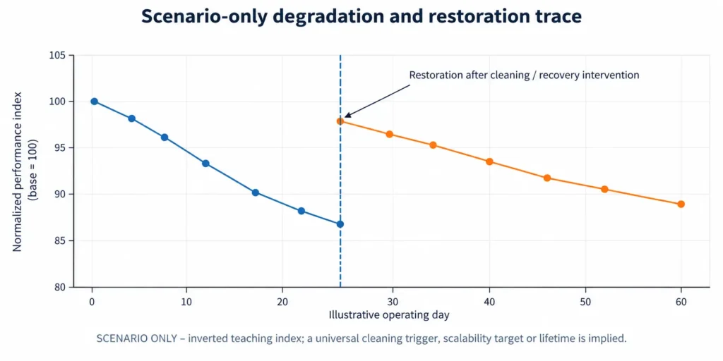
Figure 35.2. Scenario-only normalized degradation trace. Trend direction and post-intervention recovery can support maintenance decisions; actual alarm, cleaning and replacement thresholds must come from the equipment, feed, evidence and guarantees.
Choose the maintenance strategy by criticality and failure behavior
DOE O&M guidance distinguishes reactive/corrective, preventive, predictive and reliability-centered maintenance, with reliability-centered maintenance combining failure behavior, operating context and cost/risk to select an appropriate strategy. IEC 60300-3-10:2025 similarly treats maintainability and maintenance as lifecycle disciplines connected to reliability, availability and supportability.
The correct strategy therefore differs by asset. Run-to-failure can be rational for a non-critical, quickly replaceable item with safe redundancy. It is irrational for a unique brine transfer pump, critical analyzer, crystallizer circulation component or control-system part whose failure can stop the water/residual obligation for weeks.
| Strategy | Use when | Evidence / trigger | MLD/ZLD examples | Main control |
|---|---|---|---|---|
| Reactive / run-to-failure | Failure is safe, detectable, low consequence and rapidly recoverable. | Failure event. | Low-criticality auxiliary with stocked replacement and no service impact. | Prove redundancy, isolation and replacement time. |
| Preventive | Age/time/cycle has a defensible relationship to failure or required statutory/vendor task. | Calendar, hours, starts or cycles. | Lubrication, periodic inspection, planned consumable replacement. | Avoid intrusive maintenance that creates more risk than it removes. |
| Predictive / condition-based | Condition can be measured early enough to plan intervention. | Trend or diagnostic threshold on valid data. | Vibration, corrosion inspection, normalized membrane/heat-transfer performance. | Define measurement quality and response lead time. |
| Reliability-centered | Failure consequences and modes justify a mixed strategy. | Criticality + failure-mode analysis + operating context. | Critical pumps, thermal train, controls, solids handling, essential analyzers. | Link strategy to safety, environment, service and lifecycle cost. |
Table 35.6. Maintenance strategy should follow failure consequence, detectability and restoration needs—not a site-wide preference for one method.
Membrane cleaning is an engineered restoration procedure
Membrane cleaning should have a defined reason, compatible chemistry, circulation and soak conditions, waste route, verification method and acceptance criterion. Current DuPont FilmTec materials explicitly cover RO/NF operation, cleaning, sanitization and troubleshooting, but the chemical limits and cleaning methods are product- and service-specific. The owner should therefore preserve the selected membrane supplier’s current limits and the demonstrated pilot/commissioning basis rather than copying generic CIP recipes into the operating manual.
The operating decision is not merely “when to clean.” It is whether the signal is real, whether fouling or scaling is the likely mechanism, whether the cleaning train can reach each pressure vessel or module as intended, whether cleaning waste can be contained, and whether performance is restored without accelerating damage.
| Cleaning control | Required basis | Pre-clean check | Post-clean check | Failure signal |
|---|---|---|---|---|
| Trigger | Normalized performance or inspected condition tied to the specific system. | Confirm feed and instrument effects; verify hydraulic state. | Compare on the same normalized basis. | Cleaning is triggered by raw flow alone. |
| Chemistry | Membrane/material compatibility, foulant hypothesis and supplier limits. | Chemical concentration, temperature, pH and storage quality. | Rinse clearance, integrity and product water quality. | Recipe is generic or outside material limits. |
| Hydraulics | Required flow, pressure, direction, staging and vessel coverage. | CIP pump/tank/filters and line-up. | Evidence that the full train was contacted and rinsed. | Cleaning skid cannot deliver the specified duty. |
| Waste | CIP volume, composition, neutralization/segregation and destination. | Available tank/fallback capacity. | Waste accounted in residual balance. | Cleaning creates an unplanned discharge. |
| Restoration | Defined performance, integrity and quality checks. | Pre-clean baseline and sample plan. | Recovery, residual deviation and next action. | “Looks better” substitutes for measurable recovery. |
Table 35.7. A membrane CIP is a controlled intervention with a trigger, mechanism hypothesis, compatible procedure, waste route and measurable restoration test.
Evaporator and crystallizer cleaning must be designed with solids and downtime
Thermal concentration equipment should be designed around the reality that heat-transfer surfaces, circulation paths, nozzles, separators and solids-handling equipment will accumulate deposits or experience changing slurry behavior. The cleaning basis therefore belongs in the mechanical layout, isolation philosophy, drains, access, lifting, chemical/water supply and residual storage—not only in an O&M manual written after construction.
Cleaning method and frequency are project-specific. The chapter deliberately avoids generic fouling factors, cleaning intervals or chemical recipes because feed chemistry, temperature, supersaturation strategy, materials and crystallizer type govern the mechanism. The operating record should instead connect observed duty loss or solids behavior to inspection, chemistry, clean-out findings and post-clean restoration.
| Mechanism / area | Operating evidence | Design-for-maintenance feature | Cleaning / restoration record | Residual created |
|---|---|---|---|---|
| Heat-transfer surface deposition | Comparable-duty heat/energy trend, temperatures and inspection. | Isolation, access, drainability and cleaning circulation. | Deposit description, method, duration and recovered duty. | Cleaning liquor / dislodged solids. |
| Circulation / line plugging | Pressure/flow change, pump load, slurry condition and inspection. | Flush points, line geometry, isolation and accessible wear sections. | Cause, removed mass/material and restart condition. | Flush liquor / wet solids. |
| Separator / demister fouling | Carryover, condensate quality, pressure or visual inspection. | Access, wash connection and controlled drain. | Condition and post-wash separation quality. | Wash water with concentrated contaminants. |
| Crystallizer solids instability | PSD/phase, slurry density, yield, mother-liquor and centrifuge/filter behavior. | Sampling, purge control, seed/start-up and clean-out provision. | Campaign history, solids balance and recovery action. | Off-spec crystals / mother liquor / wash. |
| Solids-handling build-up | Throughput, torque/load, moisture and storage behavior. | Access, dust/wash control, bypass or buffer capacity. | Clean-out time and impact on plant availability. | Salt/sludge or contaminated wash. |
Table 35.8. Thermal and crystallization cleaning must be integrated with access, isolation, residual capacity and measurable restoration.
Spares, redundancy and supportability convert repair time into an availability decision
IEC 60300-3-14:2024 frames supportability and support as lifecycle activities used to balance performance, cost and risk, while IEC 60300-3-10:2025 links maintainability to availability and support. In practice, a redundant pump does not protect availability if both trains share the same vulnerable electrical component, analyzer, control module, seal material or vendor-only tool.
Spares should therefore be selected from criticality, failure mode, installed population, lead time, shelf life, repair capability, common-mode exposure and consequence—not from a vendor’s generic recommended-spares percentage. The register must also distinguish commissioning spares, operating spares, insurance/strategic spares and consumables.
| Support item | Selection basis | Minimum record | Review trigger | Failure prevented |
|---|---|---|---|---|
| Commissioning spares | Expected start-up damage, adjustments and punch-list risk. | Quantity, storage and consumption/replenishment. | Commissioning closeout. | Start-up delays for minor failures. |
| Operating spares | Failure frequency, installed population and repair time. | Part number, equipment mapping, min/max and lead time. | Consumption trend / design change. | Routine maintenance outage extended by procurement. |
| Strategic / insurance spares | Low-frequency but high-consequence item with long supply or repair time. | Criticality, preservation, test/rotation and ownership. | Supplier lead time, obsolescence or risk change. | Single failure disables service for months. |
| Consumables / chemicals | Usage, delivery reliability, shelf life and storage constraint. | Normal/design consumption, reorder point and alternate source. | Demand variance or supply disruption. | Plant trips because a low-value consumable is unavailable. |
| Tools / software / licenses | Special tooling, diagnostic access, passwords, firmware and vendor dependence. | Owner access, backups, expiry and support terms. | Update/obsolescence / contract expiry. | Owner cannot diagnose or restore equipment. |
Table 35.9. Supportability should be built from criticality, lead time, common-mode risk and restoration time—not a generic spares allowance.
Corrosion inspection must follow the actual materials and service
Chapter 34 required a material-by-service schedule tied to feed chemistry, temperature, pressure, cleaning exposure, stagnant conditions and credible upsets. Operations must turn that schedule into an inspection plan. The purpose is not to assign one generic corrosion rate; it is to identify where degradation can occur, how it will be detected before loss of containment or performance, and what condition requires repair, replacement or materials review. [BC-34]
| Inspection field | Required basis | Method example | Decision output | Failure if absent |
|---|---|---|---|---|
| Service / mechanism | Actual chemistry, temperature, oxygen/redox, solids, velocity, cleaning and stagnation. | Mechanism-specific visual/NDT/condition method. | Expected damage location and inspection scope. | Inspection looks at accessible areas rather than credible mechanisms. |
| Baseline condition | Commissioning thickness/condition, material traceability and known defects. | Baseline measurement / photos / records. | Reference for trend. | Later change cannot be distinguished from original condition. |
| Inspection interval | Criticality, mechanism rate uncertainty, previous findings and access opportunity. | Risk-based planned interval. | Next inspection and contingency. | Calendar interval has no connection to degradation risk. |
| Acceptance / action | Engineering limit, containment, performance and repair basis. | Measured/observed condition against approved criterion. | Continue, monitor, repair, replace or redesign. | Data are collected but never linked to action. |
| Feedback | Failure finding, root cause, repair material and changed service. | MOC / materials register update. | Revised inspection and spare strategy. | Same degradation repeats after repair. |
Table 35.10. Corrosion inspection should be mechanism- and service-specific, with a baseline, action criterion and feedback loop.
Salt and sludge handling are core operating systems
MLD/ZLD performance can be lost downstream of the separator. Wet sludge that cannot dewater, crystals that retain mother liquor, a blocked conveyor, an overfilled silo or rejected product with no fallback route can stop the water plant even when the concentration equipment is healthy. Solids handling therefore needs the same operating envelope, storage, maintenance and emergency logic as pumps, membranes and evaporators.
| Solids-handling duty | Routine control | Capacity / buffer question | Off-spec / upset route | O&M failure signal |
|---|---|---|---|---|
| Sludge dewatering | Feed solids, polymer/conditioning where used, cake moisture and filtrate quality. | Can dewatering absorb peak precipitation and maintenance downtime? | Wet storage, alternate dewatering or compliant disposal. | Upstream treatment must reduce load because cake handling is saturated. |
| Crystal separation / wash | Slurry feed, separation, wash ratio basis, moisture and product quality. | Can centrifuge/filter and wash systems match campaign peaks? | Rework, dissolve/recycle, downgrade or residual route. | On-spec process is throttled by separation capacity. |
| Drying / conditioning | Moisture, caking/dust, temperature and product form. | Is there enough buffer during dryer/conditioner outage? | Wet product hold or compliant residual route. | “Product” cannot be stored or transported as produced. |
| Conveying / storage | Load, level, dust, bridging and corrosion/wear. | How many hours/days of safe buffer exist under stated production? | Alternate bin/container or controlled production reduction. | A small mechanical fault shuts the liquid process. |
| Rejected / unsold material | Quarantine, identification and inventory ageing. | Can the site hold the credible rejection case? | Reprocess, secondary outlet or disposal with no revenue credit. | Water service depends on uninterrupted product dispatch. |
Table 35.11. Salt and sludge handling must preserve the treatment obligation when dewatering, separation, storage or product acceptance is degraded.
Emergency storage and degraded operation must protect the water and residual obligation
EPA’s current wastewater emergency-response resources define an emergency response plan as the strategies, resources, plans and procedures used to prepare for and respond to incidents, and the 2025 wastewater ERP template explicitly supports utility-specific planning. An industrial MLD/ZLD system should use the same discipline without copying municipal regulatory assumptions: define credible events, responsible people, communications, safe states, available storage, fallback routes and the conditions for restart.
Emergency storage is not a decorative tank volume. It must be connected to a scenario: which streams can be held, at what incoming rate, what inventory already occupies the tank, whether incompatible wastes are segregated, what happens when the storage time is exhausted, and who is authorized to reduce or stop upstream production.
| Scenario | Immediate objective | Required buffer / fallback | Decision before storage expires | Restart condition |
|---|---|---|---|---|
| Critical equipment trip | Prevent uncontrolled discharge and protect equipment. | Feed reduction/stop, segregated tankage, redundant route or permitted fallback. | Repair, switch train, curtail production or controlled shutdown. | Cause understood; protective systems and residual route available. |
| Power / utility loss | Move to safe state without damaging concentrated inventory. | UPS/control power as justified, safe depressurization/drain/heat strategy, storage. | Preserve, remove heat/load, isolate chemicals and manage inventory. | Utilities stable; equipment and chemistry within restart envelope. |
| Off-spec product / receiver loss | Keep water treatment independent from merchant acceptance. | Quarantine, rework, alternate receiver or full residual route. | Limit product train or revert to non-revenue residual basis. | Qualified route restored; backlog manageable. |
| Analyzer / control failure | Avoid operating blind outside critical envelope. | Redundant/cross-check measurement or conservative manual mode. | Repair/calibrate, reduce load or stop affected train. | Measurement integrity and permissives restored. |
| Residual handling outage | Prevent upstream accumulation from exceeding containment. | Sludge/salt buffer, alternate handling/disposal or controlled turndown. | Restore handling or reduce/stop feed. | Backlog and capacity returned to controlled range. |
Table 35.12. Emergency planning should convert each credible event into a safe state, finite buffer, decision deadline and restart criterion.
Shutdown, preservation and restart require controlled state transitions
High-salinity systems can change while idle: solids settle, concentrated liquor cools or crystallizes, membranes dry or foul, chemicals degrade, corrosion conditions change and residual tanks continue to fill. Shutdown and restart should therefore be treated as operating states with controlled inventories, preservation conditions, line-up, verification and release—not simply an OFF/ON command.
| Operating state | Minimum controlled actions | Inventory / chemistry concern | Release to next state | Record |
|---|---|---|---|---|
| Planned short stop | Reduce feed, stabilize recycle/purge, flush or preserve defined equipment, secure solids handling. | Settling, supersaturation, stagnant concentration and tank headroom. | Utilities/equipment ready and inventories inside restart range. | Shutdown checklist and residual inventory. |
| Extended outage | Preservation, drainage/flush where required, chemical/storage management, inspection access and spares work. | Long-term material compatibility, biological/fouling risk, precipitation and chemical shelf life. | Preservation removed correctly; inspection/maintenance closeout complete. | Outage preservation and recommissioning plan. |
| Emergency trip | Achieve safe state; isolate hazards; route incoming/residual streams. | Uncontrolled thermal/hydraulic transition and finite storage. | Incident cause controlled; equipment and containment verified. | Trip sequence, alarms, actions and incident review. |
| Degraded operation | Operate defined reduced duty with heightened monitoring and explicit time limit. | Lower redundancy, storage drawdown, quality or maintenance margin. | Normal configuration restored or planned controlled shutdown. | Deviation approval, duration, controls and exit condition. |
| Restart | Verify line-up, utilities, chemistry, instruments, interlocks, residual routes and downstream readiness. | Concentrated inventory and solids can make start-up different from steady state. | Sequential acceptance of each block and product/residual quality. | Restart checklist, samples and stabilization time. |
Table 35.13. Shutdown, preservation, degraded operation and restart should be treated as controlled process states with explicit entry and exit criteria.
Use CMMS, historian and review routines to turn operating data into learning
Asset data have value only when they support decisions. ISO 55013:2024 focuses on managing data to support asset-management objectives, and EPA asset-management guidance for water and wastewater systems links asset inventories, O&M tasks and long-range planning to sustainable service. The operating system should therefore connect work orders, alarms, laboratory results, process historian data, spare consumption, failures and changes by equipment and process state.
Avoid dashboards filled with target numbers that have no decision rule. For each O&M metric, state the denominator, operating state, owner, review frequency and action. A site may choose service availability, planned/unplanned downtime, repeat failures, cleaning recovery, maintenance compliance, chemical use, residual backlog, alarm quality or other indicators, but the guide does not prescribe universal targets.
| O&M measure | Denominator / context | What it can reveal | Review question | Action output |
|---|---|---|---|---|
| Service delivered | Required water/residual duty by operating state. | Whether the asset meets its actual obligation. | Which losses are technical, maintenance, upstream, downstream or commercial? | Constraint-removal / capacity / contract action. |
| Unplanned downtime | Hours by cause, asset, event and lost service. | Reliability and recovery weaknesses. | Are repeat causes or long restoration times dominating? | RCM/engineering/spares/support action. |
| Maintenance compliance | Planned work by criticality and due window. | Backlog and risk accumulation. | Is deferment intentional and risk-controlled? | Prioritization and resource plan. |
| Cleaning restoration | Normalized pre/post condition and waste/time. | Whether cleaning restores performance and when mechanism is changing. | Is cleaning effective, too frequent or masking another cause? | Procedure/feed/materials redesign or replacement review. |
| Laboratory / analyzer quality | QC/calibration status and decision-critical tags/methods. | Whether control data are trustworthy. | Which data gaps can invalidate process decisions? | Repair/calibration/method/escalation. |
| Residual backlog | Mass/volume against available storage and route capacity. | Whether solids/product/residual handling constrains water service. | How close is the system to a routing bottleneck? | Dispatch, fallback or production adjustment. |
| Repeat alarms / overrides | Alarm/event count by state and cause. | Nuisance alarms, bad actors and normalized abnormality. | Are operators routinely working around the design? | Alarm rationalization / control / engineering MOC. |
Table 35.14. O&M metrics should connect a denominator and operating context to a review question and action—not become decorative dashboards.
Operations and maintenance acceptance gate
The plant is operationally ready only when the owner can execute the as-awarded operating, laboratory, maintenance, cleaning, support, materials and failure-recovery basis with competent people and controlled data. A high automation level, OEM service contract or large spare-parts list cannot compensate for an undefined residual route, inaccessible maintenance task or restart sequence that has never been demonstrated.
| Gate field | Proceed | Conditional / recycle | Stop | Required record |
|---|---|---|---|---|
| People / competency | Critical tasks have qualified primary and backup owners. | One specialist dependency has a dated training/support closure. | Routine duty requires unavailable competence or single-person knowledge. | Competency and task matrix. |
| Monitoring / laboratory | Decision-critical measurements, methods and calibration/QC are controlled. | Secondary method/tag awaits improvement with bounded manual control. | Plant cannot verify its operating envelope, product/residual quality or degradation. | Instrument/lab control plan. |
| Maintenance / cleaning | Tasks are accessible, isolated, resourced and linked to restoration criteria. | One non-critical maintenance task needs planned redesign. | Availability depends on impossible access or unproven cleaning/restoration. | Maintenance/CIP plan and job plans. |
| Spares / support | Critical restoration paths, spares, tools, data rights and support are available. | One long-lead exposure is mitigated temporarily. | Single foreseeable failure creates uncontrolled long outage or vendor lock-in. | Critical spares/support register. |
| Materials / degradation | Mechanisms, baselines, inspection points and action limits are owned. | One secondary mechanism requires early-life inspection. | Credible degradation has no detection or containment strategy. | Materials/inspection plan. |
| Residual / solids / emergency | Routine and upset solids/liquid/product routes have finite capacity and fallback. | A contingency route is time-limited but controlled. | Water service requires unbounded storage or uninterrupted product dispatch. | Residual and emergency-capacity plan. |
| Shutdown / restart | Normal, degraded, emergency and restart states are documented and demonstrated appropriately. | One scenario awaits planned drill or commissioning evidence. | Safe state or restart sequence is undefined. | Operating-state procedures and test record. |
| Learning / governance | CMMS, historian, deviations, failures, MOC and review ownership are active. | Data integration improvement does not impair immediate control. | Recurring workarounds and failures are not captured or governed. | O&M performance and change-control record. |
Table 35.15. O&M readiness advances only when people, data, maintenance, support, residuals and failure recovery can sustain the service obligation.
Stop ruleStop, redesign or re-stage when the water/residual obligation depends on unavailable operator competence, untrusted measurements, inaccessible maintenance, unproven cleaning, a single unsupported spare or vendor interface, uncontrolled degradation, inadequate solids/residual capacity, or an undefined safe shutdown/restart path. Do not call a plant operable because it can run at steady state on commissioning day. |
|---|
Handover to Chapter 36 – why MLD and ZLD projects fail
Chapter 36 examines failure mechanisms candidly. It should receive actual O&M burdens and precursors rather than a retrospective label of “operator error.” The master brief identifies recurring failure themes such as ignored variability, TDS-only design, underestimated silica/sulfate and corrosion, antiscalant overconfidence, mother-liquor accumulation, weak solids testing, assumed salt sales, missing residual costs and operator/guarantee/downtime failures. [BC]
The handover from Chapter 35 should show which design assumptions became daily work, which were difficult to control, which failure modes produced repeat interventions, how cleaning and degradation evolved, where residual or product handling constrained water service, and whether operators had the competence, instrumentation, spares, procedures and contractual support that the design assumed. That evidence lets Chapter 36 distinguish a true equipment failure from a framing, interface, operating-model or business-case failure.
| Handover field | Required basis for Chapter 36 | Failure question enabled |
|---|---|---|
| Operator burden / capability | Actual rounds, interventions, specialist dependencies, training gaps and workarounds. | Was the plant designed for the owner’s real capability? |
| Monitoring / laboratory | Critical tags/methods, bad data, alarm burden, calibration/QC and missed precursors. | Did the project detect the chemistry and degradation it claimed to control? |
| Degradation / cleaning | Trend, mechanism, cleaning frequency basis, restoration, waste and replacement. | Was deterioration anticipated, diagnosable and recoverable? |
| Availability / downtime | Events by cause, lost service, restoration time, redundancy and common-mode failures. | Did reliability/support assumptions survive operation? |
| Materials / corrosion | Inspection findings, leaks/damage, repairs, service changes and root cause. | Were real chemistry and cleaning exposures reflected in materials selection? |
| Solids / residuals | Sludge/salt throughput, storage, off-spec, disposal and bottlenecks. | Did the project solve liquid disposal by creating an unmanageable solid/product system? |
| Emergency / restart | Trips, storage use, degraded operation, shutdown/restart and incident learning. | Could the plant fail safely and recover predictably? |
| Commercial dependency | Product rejection, receiver outages, logistics and no-revenue fallback use. | Did commercial assumptions ever endanger the treatment obligation? |
Table 35.16. Chapter 36 needs operating evidence that distinguishes equipment failure from failures of framing, capability, residual design, interfaces and commercial assumptions.
Chapter conclusion
Operations and maintenance are not the phase after engineering; they are the test of whether the engineering was complete. A maintainable MLD/ZLD plant has an observable operating envelope, competent task owners, fit-for-purpose laboratory and measurement systems, maintenance and cleaning procedures that can actually be executed, critical spares and support, mechanism-based materials inspection, robust solids handling, finite emergency capacity and controlled shutdown/restart states.
Predictability comes from connecting these elements. Normalized trends distinguish changing feed from changing equipment. Work orders and inspections turn degradation into planned intervention. Spares and access convert failure into a bounded outage. Emergency storage and fallback routes prevent an equipment event from becoming an environmental event. Learning systems prevent temporary workarounds from becoming permanent design conditions.
Chapter 36 now uses this operating evidence to explain why MLD and ZLD projects fail – often because the project framed, guaranteed or commercialized the wrong problem before the equipment ever had a chance to prove itself.
Chapter 35 in one sentenceA large MLD/ZLD plant is operable only when competent people, trustworthy data, maintainable equipment, controlled cleaning, spares, materials inspection, residual capacity and predictable failure recovery are designed as one system. |
|---|