
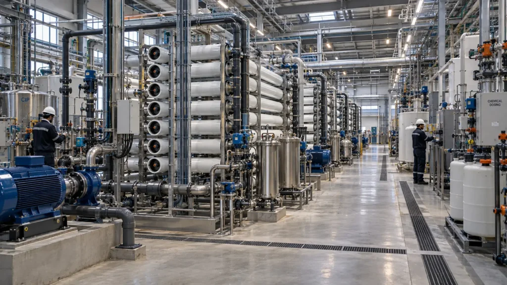
Define the roles and limits of RO, NF, closed-circuit and batch RO, and ED/EDR without treating them as interchangeable salt-removal boxes.
Controlled principleMembrane selection begins with the required separation: water from salts, multivalent ions from monovalent ions, a defined reduction in ionic load, or a split that protects the next unit. Recovery, rejection and energy are properties of a complete staged system under a stated feed and operating envelope—not permanent attributes of a membrane label. |
|---|
16.1 Start with the separation objective and system location
Chapter 15 delivered a conditioned feed, residual ledger and list of intentionally unresolved constraints. Chapter 16 decides whether a conventional membrane block can perform the next separation at a defensible recovery and availability. The first decision is not the membrane brand. It is the required transfer of water and ions across the system boundary.
RO is normally selected when broad dissolved-salt rejection and a low-salinity permeate are required. NF is selected when multivalent ions, selected organics or hardness should be rejected while a useful fraction of monovalent ions passes. ED and EDR move ions through ion-exchange membranes under an electric field and can provide adjustable partial desalting or ion redistribution while most water remains in the liquid channels. Closed-circuit, semi-batch and batch RO alter the hydraulic path and pressure history rather than changing the underlying RO membrane chemistry.
System location changes the value of selectivity. NF upstream of RO can reduce multivalent scale formers but also creates an NF concentrate and may sacrifice ions or products that should remain in the main train. NF after selective precipitation can polish residual multivalents while preserving a sodium-chloride-rich feed for deeper concentration. ED/EDR can be a primary brackish-water process, a polishing step or a concentrate-management block. The correct position follows the ion target and the residual route.
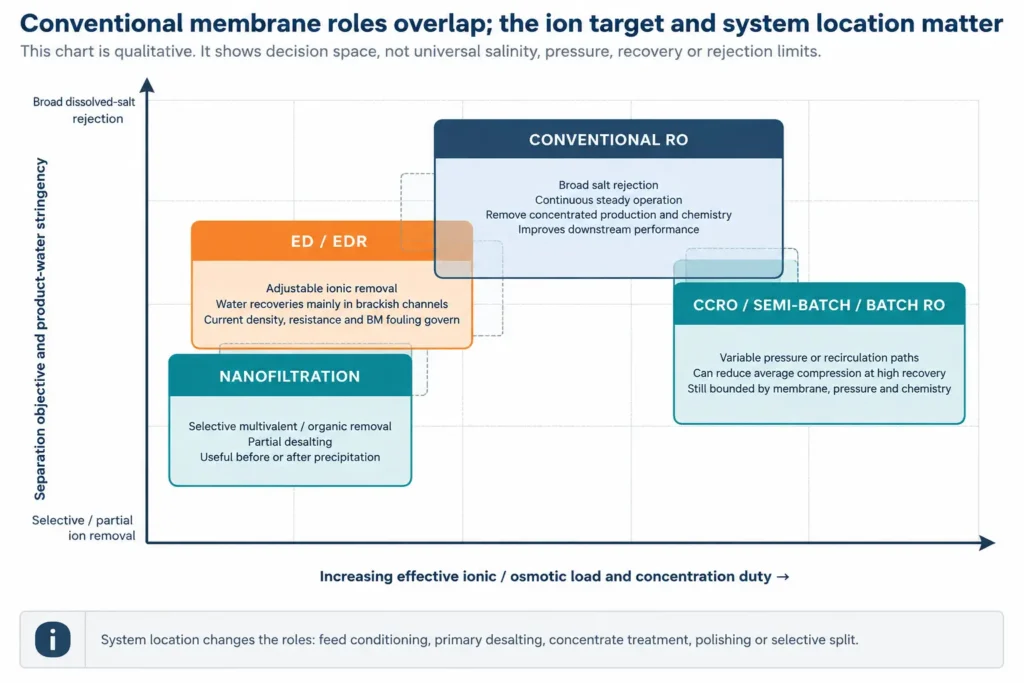
Figure 16.1. Qualitative conventional-membrane operating window. The zones overlap and do not represent universal numerical limits.
| Technology / configuration | Primary transported species | Best role | Product and residual | Main constraint | Evidence before selection |
|---|---|---|---|---|---|
| RO | Water permeates; most dissolved ions and many organics are retained to membrane-specific degrees. | Broad desalting and water recovery. | Low-salinity permeate plus a concentrated liquid. | Net driving pressure, concentration polarization, scaling/fouling, pressure rating and permeate specification. | Projection with full chemistry; staged hydraulic design; pilot/comparable reference; cleaning and residual route. |
| NF | Water and selected monovalent ions pass more readily; multivalent ions and some organics are preferentially retained. | Hardness/sulfate/organic separation or selective conditioning. | Partially demineralized permeate and multivalent-rich concentrate. | Charge, pH, ionic strength, membrane chemistry and competition between ions. | Ion-by-ion passage across operating cases; mass balance and value of both streams. |
| Conventional staged RO | Same membrane mechanism as RO; vessels and stages distribute flow, pressure and recovery. | Continuous high-throughput desalting with proven equipment architecture. | Combined permeate and final concentrate; interstage pressure/flow changes. | Uneven flux, tail-end concentration, pressure drop and stage-specific fouling. | Element-level projection, stage flux/loading, ERD/pump design and normalized monitoring plan. |
| CCRO / semi-batch RO | RO separation with recirculation and a time-varying concentration path. | Higher recovery or lower average overpressure within a conventional RO pressure class. | Permeate during the cycle and a discharged concentrate batch. | Mixing, cycle hydraulics, flush/displacement, peak pressure and chemistry at cycle end. | Vendor/system model plus cyclic mass balance, event testing, controls and concentrate discharge logic. |
| Batch RO | RO separation with a finite batch and pressure that can follow rising osmotic pressure. | Energy-efficient high-recovery operation where batch equipment and control are justified. | Permeate over the batch plus a final concentrate and displacement/flush streams. | Pressure exchanger/work-exchanger volume, dead volume, backflow, cycling and scale-up maturity. | Pilot-scale cyclic performance at representative salinity, recovery, fouling and throughput. |
| ED / EDR | Ions migrate through cation- and anion-exchange membranes; water largely remains in diluate/concentrate channels. | Adjustable partial desalting, ionic load reduction or selected ion separation. | Diluate and ion-enriched concentrate; electrode/cleaning streams depend on system. | Electrical resistance, limiting current, water transport, IEM selectivity, scaling and organic fouling. | Stack projection, current efficiency, voltage/current limits, flow distribution, reversal/cleaning and both-stream quality. |
Table 16.1. Technology roles are defined by transported species, product specification and system location.
16.2 Reverse osmosis: pressure must overcome the local osmotic difference
RO produces water flux when the hydraulic-pressure difference across the membrane exceeds the opposing osmotic-pressure difference. The useful driving force is therefore not the feed-pump discharge pressure alone. It is the local net driving pressure after feed-channel pressure loss, permeate pressure and concentration polarization are accounted for. The membrane surface can see a higher salt concentration than the bulk channel, particularly at high flux and toward the concentrate end of a stage.
The ideal NaCl calculation below illustrates the physical direction of the problem: osmotic pressure rises with concentration, so the hydraulic duty increases and the available margin for water flux narrows. It is not a design equation for industrial brines. Mixed ions, activity coefficients, density, temperature, precipitation and membrane-surface concentration must be represented with appropriate software and test data.
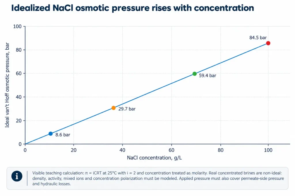
Figure 16.2. Idealized osmotic-pressure calculation for NaCl. The stated assumptions exclude concentrated-brine non-ideality.
| RO design field | What must be calculated | Why it changes through the train | Failure if simplified | Required check |
|---|---|---|---|---|
| Net driving pressure | Feed/permeate pressures, local osmotic pressure and channel losses. | Feed pressure falls while concentrate osmotic pressure rises. | Front-end overflux or tail-end loss of production and quality. | Element/stage projection with normal, design and turndown cases. |
| Water flux distribution | Element-area loading, temperature correction and recovery by element/stage. | Permeability and driving force vary along the vessel. | Fouling at the lead element and scaling at the tail. | Flux/loading limits from the selected supplier and comparable service. |
| Salt passage / permeate quality | Ion-specific passage, permeate backpressure, temperature and concentration. | Passage can rise with concentration, temperature and membrane ageing. | Average permeate meets TDS while a critical ion fails specification. | Ion-by-ion permeate prediction and sample plan. |
| Concentration polarization | Mass-transfer coefficient, spacer/channel hydraulics and surface concentration. | Flux and concentration increase the surface-to-bulk gradient. | Underpredicted osmotic pressure and saturation at the membrane. | Model sensitivity plus pilot/normalized operating evidence. |
| Pressure drop and crossflow | Feed-spacer pressure loss, viscosity, flow, fouling and stage hydraulics. | Concentrate viscosity and deposits alter channel resistance. | Compaction, spacer blockage, telescoping or inadequate shear. | Supplier limits, clean/dirty curves and differential-pressure alarms. |
| Recovery and concentrate | Stage/overall/net recovery, chemical additions, cleaning use and purge. | Every stage changes flow and chemistry; availability changes annual recovery. | Nominal recovery hides CIP, off-spec periods and residual-water use. | Chapter 9 definitions and full residual ledger. |
Table 16.2. RO design fields that must be resolved by stage and operating case.
16.3 Nanofiltration: selectivity is the product
NF is not simply a lower-pressure RO. Its value lies in differential solute transport. Current DuPont material describes high rejection of multivalent ions and lower rejection of monovalent ions, while also noting that feed concentration, temperature, pH, pretreatment and membrane type affect performance. Product data sheets—not the generic NF label—control the actual pressure, pH, temperature and cleaning envelope.
Ion passage depends on size, charge, membrane charge, ionic strength, pH, concentration, competing ions and concentration polarization. A sulfate-removal NF may behave differently when the same TDS is redistributed among sodium chloride, magnesium sulfate, organics and antiscalant. The design should therefore show individual ion loads in both permeate and concentrate and state which stream is valuable.
NF position should be justified against the full train. Upstream NF can protect RO from divalents but increases the NF hydraulic duty and creates a concentrated multivalent residual. Downstream NF after precipitation can polish residual hardness or sulfate and preserve monovalent salts for an RO, ED or thermal block. The preferred location is a mass-balance and business-case decision.
| NF question | Required evidence | Permeate consequence | Concentrate consequence | Decision error to avoid |
|---|---|---|---|---|
| Which ions must pass and which must remain? | Ion-by-ion specification and passage over the full chemistry envelope. | May retain useful monovalent salt or fail a critical ion target. | Can enrich scale formers, metals or valuable ions. | Selecting NF by nominal molecular-weight cut-off alone. |
| Where should NF sit? | Before/after precipitation, RO, ED or product recovery with closed balances. | Changes osmotic load and downstream water quality. | Changes residual volume, purity and disposal route. | Assuming upstream NF is always protective or always lower-energy. |
| How does pH/ionic strength change selectivity? | Representative tests or validated projection at operating conditions. | Ion passage and organic rejection can shift. | Composition may be less stable than TDS suggests. | Using single-salt datasheet rejection for a mixed brine. |
| Can both streams be used or managed? | Named internal use, buyer/specification or disposal route for each stream. | Partial desalting may be the intended product. | Multivalent-rich concentrate may be the true project constraint. | Valuing only permeate and ignoring concentrate chemistry. |
Table 16.3. NF selection requires an ion-by-ion product and residual specification.
16.4 Continuous staging: distribute recovery rather than average it
A conventional RO train distributes membrane area, pressure vessels and feed flow across stages. The objective is to maintain acceptable element flux, crossflow, pressure drop and concentrate chemistry from the first element to the last. A plant-wide recovery number cannot reveal whether the lead elements are overloaded or whether the final stage crosses a scaling or pressure boundary.
Interstage boosting, concentrate recycle, flow reversal, permeate backpressure, staged chemical addition and multiple passes can each alter the operating window. They also add pumps, controls, mixing and non-routine streams. WAVE and similar supplier tools are useful for element-level projections, but the model must use the actual feed analysis and selected product data.
| Staging decision | Benefit sought | New equipment / control | New residual or loss | Failure mode | Verification |
|---|---|---|---|---|---|
| Additional stage | Distribute area and recover more water at lower local flux. | Vessels, piping, valves and instrumentation. | Additional flush/CIP volume and concentrate inventory. | Tail-stage scaling, low crossflow or poor permeate quality. | Element-level flux, pressure and saturation projection. |
| Interstage boost | Restore driving pressure for a later stage. | Booster pump, controls and electrical load. | Pump losses and maintenance. | Overpressure or inadequate pressure during variable operation. | Pressure rating and transient analysis. |
| Concentrate recycle | Increase crossflow or modify feed concentration. | Recycle pump, mixing and control. | Higher internal flow, chemical recirculation and accumulation. | Hidden recovery basis, temperature rise and unresolved purge. | Closed water/salt balance and steady-state accumulation model. |
| Multiple pass | Improve permeate quality or target a difficult ion. | Second-pass pump/membranes and blending. | Second-pass concentrate and product-water use. | Good final quality with poor overall recovery or residual route. | Overall/net recovery and combined permeate specification. |
| Flow reversal / switching | Redistribute lead/tail exposure and deposits. | Valving, automation and transition management. | Transition/off-spec water and flush. | Hydraulic shock, mixing or control failure. | Cyclic test and product-diversion logic. |
Table 16.4. Continuous RO staging decisions and the additional duties they create.
16.5 Closed-circuit, semi-batch and batch RO
Closed-circuit and semi-batch systems recirculate concentrate while withdrawing permeate, then discharge a concentrated batch and reset the circuit. Batch systems use a finite feed volume and can vary pressure as osmotic pressure rises. Both approaches can reduce the average excess pressure relative to a conventional constant-pressure train, particularly at high recovery, but they introduce cyclic mixing, displacement, valve, tank/work-exchanger and control duties.
DuPont’s current WAVE CCRO documentation treats CCRO as conventional RO with a different flow calculation and lists a recommended recovery range of 75–98%, a broader valid range of 50–99.9%, a maximum pressure of 41 bar and a standard design below 31 bar for that specific product/configuration. These are vendor-controlled design values, not generic limits for all CCRO or batch systems.
A 2024 direct experimental comparison of batch, semi-batch and hybrid modes used the same membrane and pump and reported lower electrical SEC for batch/hybrid operation under the tested seawater and brackish-water conditions. For brackish water at recoveries of 0.90–0.94, the reported hybrid SEC was 1.81–2.02 kWh/m³, 22–32% below the semi-batch baseline. The study is valuable evidence of mechanism and scale-up potential; it is not a project benchmark without the tested feed, pressure, work-exchanger volume and throughput.
| Cyclic-system field | Why it matters | Minimum model / test | Residual or transition stream | Scale-up question |
|---|---|---|---|---|
| Cycle mass balance | Concentration, volume and permeate quality change continuously. | Time-step water/ion balance including dead volume and mixing. | Final concentrate, displacement and first-flush water. | Does the full cycle close at production scale? |
| Pressure path | Energy benefit depends on matching pressure to rising osmotic pressure. | Pump/ERD efficiency map and transient pressure control. | Energy losses and possible off-spec transition water. | Can equipment follow the pressure/flow trajectory reliably? |
| Work exchanger / recirculation volume | Volume affects mixing, backflow, throughput and energy. | Hydraulic model plus pilot measurements. | Residual volume in pipework and exchanger. | Does equipment size erase the theoretical benefit? |
| End-of-cycle chemistry | Peak salinity, saturation, viscosity and passage occur near discharge. | Representative end-point samples and scale/fouling tests. | Most concentrated liquid and cleaning burden. | Can the cycle repeat without progressive accumulation? |
| Availability and controls | More valves and cycling can add downtime or transition losses. | Failure-mode analysis, bypass/diversion and automated sequence tests. | Off-spec product and partially processed batches. | Is effective annual recovery better than a simpler train? |
Table 16.5. Closed-circuit and batch RO require a cyclic rather than steady-state design basis.
Current bounded examples—not universal performance rangesDuPont WAVE CCRO values apply to its stated configuration and pressure class. The 2024 batch-RO SEC values apply to the tested membrane, pressure, salinity, recovery and work-exchanger volumes. Energy-recovery-device efficiencies apply to named products and operating conditions. The project basis must retain those boundaries rather than convert them into generic “typical” values. |
|---|
16.6 Electrodialysis and electrodialysis reversal
ED applies an electric field across alternating cation- and anion-exchange membranes, creating diluate and concentrate channels. The primary transported species are ions rather than water. This makes ED fundamentally different from RO: the electrical duty scales with ionic transport and resistance, and the product can be defined as a specified reduction in ionic load rather than near-total salt rejection.
EDR periodically reverses polarity and hydraulic roles to reduce persistent scale and fouling. Current Water Technologies material presents EDR as a high-recovery brackish-water technology with adjustable product performance, silica tolerance and the ability to handle feed variability. Those are vendor claims for a product family, not universal guarantees. The EDR literature also shows that reversal does not eliminate all fouling: organic matter, metal–organic complexes, particles and biological material can still produce irreversible or asymmetric membrane fouling.
The ED/EDR design should state the required diluate conductivity or ion load, concentrate composition, current efficiency, electrical resistance, current-density/limiting-current margin, water transport, membrane selectivity, channel pressure drop, reversal sequence, electrode-stream chemistry and cleaning strategy. Monovalent-selective membranes may create valuable splits, but selectivity and economics must be demonstrated in the complete matrix.
| ED/EDR field | Design basis | Failure mechanism | Product / residual effect | Required evidence |
|---|---|---|---|---|
| Voltage, current and resistance | Feed/diluate/concentrate conductivity, stack resistance, temperature and current efficiency. | Excess voltage, heating or poor energy efficiency. | Higher ionic removal or higher concentrate load. | Stack model and measured current–voltage response. |
| Limiting-current margin | Concentration polarization and minimum local diluate concentration. | Water splitting, pH shift, scale and membrane damage. | Off-spec diluate and chemically altered concentrate. | Local/current-density design and pilot monitoring. |
| Ion selectivity | IEM chemistry, valence, competing ions, pH and target split. | Unexpected co-ion leakage or target contamination. | Determines whether either stream is a product. | Ion-by-ion mass balance and product qualification. |
| Water transport | Electro-osmosis, osmosis and hydraulic imbalance. | Loss of recovery or channel overflow/underflow. | Changes diluate/concentrate volumes independently of ion transfer. | Full water balance by stage and reversal period. |
| Scaling and fouling | Ca/Mg/sulfate/carbonate, organics, particles, biology and reversal logic. | Deposits, resistance rise, flow maldistribution and irreversible fouling. | Cleaning waste and reduced current efficiency. | Representative pilot, pressure drop, resistance and membrane autopsy. |
| Electrode and reversal streams | Electrode chemistry, gas generation/control, rinse and transition sequence. | Unsafe gas, pH/redox excursion or cross-contamination. | Electrode rinse and transition/off-spec water. | Vendor design, materials and HAZOP. |
Table 16.6. ED/EDR design fields and the product/residual consequences of ion transport.
16.7 Osmotic pressure, energy and energy recovery
RO electrical energy includes feed pumping, interstage boosting, recirculation, pretreatment, flushing and product handling. The denominator must state whether SEC is per cubic metre of feed, permeate, net recovered water or brine eliminated. Energy recovery is most valuable where a pressurized concentrate leaves the membrane block.
Isobaric pressure exchangers transfer pressure from concentrate to incoming feed. Energy Recovery currently reports up to 98% efficiency for its PX Q400 product and markets separate devices for low-pressure and ultra-high-pressure applications. These are vendor-specific product values. The project calculation must use the selected device’s flow, pressure, salinity, mixing, leakage and booster-pump requirements.
ED/EDR energy is primarily electrical work for ion transport plus hydraulic pumping. It is not usefully compared with RO using one universal kWh/m³ number because the salt removed, feed/product concentration, recovery and current efficiency differ. Technology comparison should use the same feed, product specification, residual endpoint and system boundary.
| Energy field | RO / NF basis | ED / EDR basis | Common accounting error | Required output |
|---|---|---|---|---|
| Driving work | Pressure × flow adjusted for pump efficiency and pressure recovery. | Voltage × current adjusted for current efficiency and auxiliary loads. | Comparing technologies at different product quality or salt removal. | Block and total-site SEC with denominator. |
| Recovery device | Concentrate pressure, flow, mixing/leakage and booster duty. | Usually not a pressure-recovery problem; electrical staging and polarity control dominate. | Using catalogue peak efficiency as annual plant efficiency. | Device/system efficiency across operating cases. |
| Hydraulic auxiliaries | Feed, recirculation, interstage, permeate and CIP pumping. | Diluate/concentrate/electrode pumping and reversal transitions. | Omitting recirculation, flush and transition energy. | Annual energy including start-up and cleaning. |
| Thermal and chemical effects | Temperature changes permeability, viscosity and pressure duty; dosing creates salt load. | Temperature changes resistance; chemicals alter conductivity and fouling. | Treating pretreatment energy/chemicals as outside the membrane option. | Integrated train energy and reagent ledger. |
| Availability | Downtime, low-load operation, off-spec water and membrane ageing. | Stack cleaning, reversal losses, membrane replacement and off-spec transitions. | Nominal SEC multiplied by nameplate output. | Effective annual net-water energy. |
Table 16.7. Energy comparison requires a common product, residual and annual-operating basis.
16.8 Permeate quality, recovery and selectivity must remain separate
Water recovery, salt rejection, target-ion rejection, product yield and volume reduction answer different questions. RO recovery can rise while permeate quality deteriorates or while effective annual recovery falls because of cleaning and off-spec diversion. NF can show modest TDS rejection while achieving the exact sulfate or hardness split the project needs. ED/EDR can meet a conductivity target while moving different ions at different efficiencies.
The project should report flow-weighted combined permeate quality and stage or cycle profiles. A composite TDS result can hide the critical ion, organic or boron/ammonia specification. Temperature, pH, membrane ageing, concentration polarization and cleaning history should remain attached to the reported rejection.
| Metric | Definition / basis | Why it can mislead | Additional metric required | Residual implication |
|---|---|---|---|---|
| Stage water recovery | Stage product water divided by stage feed water. | Does not show overall recycle, product-water consumption or downtime. | Overall and effective annual net recovery. | Stage concentrate feeds the next stage or endpoint. |
| Salt rejection | Feed-to-permeate reduction on a stated concentration or load basis. | Average TDS can hide target-ion passage and concentration changes. | Ion-specific passage and mass balance. | Rejected mass accumulates in concentrate. |
| NF selectivity | Relative passage/rejection of target and competing ions. | Single-salt tests may not survive mixed-brine competition. | Both-stream purity and recovery of target ions. | Concentrate may be valuable or more difficult to manage. |
| ED current efficiency | Useful target-ion transport relative to electrical charge. | Can remain high while water transport or co-ion leakage harms product. | Water balance, ion selectivity and energy per salt removed. | Concentrate volume and composition may shift. |
| Permeate / diluate quality | Flow-weighted product composition across stages or time. | Spot samples can miss start-up, transition and tail-stage degradation. | Time/stage profile and off-spec diversion fraction. | Off-spec water requires recycle, storage or disposal. |
Table 16.8. Performance metrics must preserve their separation, time and residual bases.
16.9 Scaling, fouling, cleaning and membrane life
Pretreatment reduces risk but does not make the membrane feed harmless. RO/NF concentration polarization elevates surface concentration and can accelerate mineral deposition, organic adsorption, biofilm growth and spacer blockage. ED/EDR reversal reduces some deposit accumulation but does not eliminate organic–metal complexes, particle fouling or biological effects.
Cleaning should be triggered by normalized performance and diagnosed foulant—not by an arbitrary calendar alone. DuPont’s FT-Norm tool emphasizes normalization because temperature, salinity and pressure change apparent productivity and rejection. A 2025 study of an end-of-life potable-reuse RO element found severe inorganic-dominated fouling after four years and showed that repeated cleaning changed permeance and rejection; it illustrates why cleaning can recover some performance while also interacting with membrane integrity.
Membrane life is not a universal number. It depends on feed and pretreatment, flux, pressure, temperature, oxidant exposure, cleaning chemistry and frequency, mechanical integrity, position in the train and product specification. A 2024 study showed that chlorine exposure can change rejection of neutral organic compounds, reinforcing that a membrane can still produce acceptable conductivity while failing a trace-organic requirement.
| Indicator | Normalize / locate | Likely mechanisms | Diagnostic evidence | Action | Waste / life consequence |
|---|---|---|---|---|---|
| Permeate-flow decline | Normalize for temperature, pressure, feed concentration and recovery; locate by stage. | Fouling/scale, compaction, lower permeability or higher osmotic pressure. | Trend, pressure profile, chemistry and cleaning response. | Correct cause; clean only with compatible sequence. | CIP waste, lost production and possible irreversible ageing. |
| Salt-passage increase | Normalize and examine ion-specific passage by stage/cycle. | Membrane degradation, seal leak, oxidation, temperature or concentration polarization. | Integrity test, probing, element test and ion fingerprint. | Isolate leak or replace/repair; protect from oxidant. | Off-spec water and spent elements. |
| Differential-pressure rise | Locate vessel/stage/channel and compare with clean baseline. | Particulate cake, biofilm, precipitate or spacer blockage. | Hydraulics, autopsy and solids identification. | Clean, adjust pretreatment/flux or replace blocked elements. | High-volume flush/CIP and damaged spacer/elements. |
| ED stack-resistance rise | Track by stack, polarity and temperature. | IEM fouling, scale, gas, flow maldistribution or membrane ageing. | Voltage/current, pressure drop, reversal response and membrane inspection. | Reverse/clean, correct feed or replace membranes/spacers. | Cleaning stream and lost current efficiency. |
| Frequent cleaning | Trend intervals and post-clean recovery. | Wrong pretreatment, unstable operation or incompatible chemistry. | Foulant identity, dose/cycle records and residual analysis. | Reframe train rather than intensify cleaning indefinitely. | Higher chemical burden, downtime and shorter membrane life. |
Table 16.9. Normalized diagnostics, cleaning response and membrane-life consequences.
Membrane-life ruleDo not publish one “typical membrane life.” State the membrane family, feed, train position, operating and cleaning history, failure criterion and replacement basis. A membrane can reach end of life through loss of flux, rejection, mechanical integrity, cleanability, product compliance or unacceptable operating cost. |
|---|
16.10 Conventional membrane acceptance gate
The membrane block can advance only when its separation duty, hydraulic/electrical design, product quality, residual stream, cleaning strategy and downside case are supported at the maturity required by the project. A projection is not a pilot, and one pilot run is not a lifetime guarantee.
| Gate field | Minimum evidence | Proceed condition | Conditional / recycle trigger | Owner / record |
|---|---|---|---|---|
| Separation duty | Ion-by-ion product and residual specification; location in the full train. | Technology mechanism matches the required split. | TDS-only target or unresolved value/route for one stream. | Process lead; basis of design. |
| Operating envelope | Normal/design/turndown/worst cases for flow, chemistry, temperature, pH and fouling. | Pressure/current, flux, recovery and materials stay within selected-product limits. | Supplier range borrowed from another feed or no transient case. | Membrane/vendor and process leads. |
| Projection and scale-up | Element/stack model, mass balance, comparable reference and representative testing. | Model and test close within stated tolerance and explain differences. | Synthetic feed only, unclosed ions or laboratory result treated as guarantee. | Technology lead; test and projection files. |
| Product quality | Flow/time-weighted permeate or diluate composition and off-spec fraction. | All critical ions/organics meet the use specification. | Average TDS passes while a critical parameter remains unproven. | Product-water owner and laboratory. |
| Residual route | Concentrate, transition, electrode, flush, CIP and spent-membrane routes. | Routine and non-routine streams have capacity and contingency. | “To waste,” unclosed recycle or product claim without user. | Residuals/environmental lead. |
| Energy and economics | Pumps, ERD, recirculation, voltage/current, auxiliaries, availability and replacements. | Integrated option survives higher-energy/lower-availability cases. | Catalogue efficiency or nominal SEC carries the business case. | Project controls and business-case owner. |
| Cleaning and life | Normalized triggers, chemical compatibility, autopsy/diagnosis plan and replacement basis. | Cleaning restores performance without unacceptable damage or waste. | Frequent cleaning, oxidant uncertainty or no end-of-life criterion. | Operations and asset-integrity leads. |
Table 16.10. Acceptance gate before advancing to high-salinity membrane processes.
16.11 Handover to Chapter 17
Chapter 17 evaluates UHPRO, OARO/COMRO, LSRRO, forward osmosis, membrane distillation and hybrid electrochemical systems. The handover from Chapter 16 is not a claim that conventional membranes have failed. It is a quantified reason why the next pressure, salinity, osmotic or selectivity regime lies outside the practical conventional window.
The handover should state the conventional option tested, selected membrane/stack, product and residual specification, maximum credible recovery, pressure/current boundary, limiting species, pretreatment, energy, cleaning, membrane life, availability and residual endpoint. Any advanced process must improve that baseline rather than compare itself with an uneconomic or deliberately misconfigured conventional train.
16.12 Chapter conclusion
Conventional membrane concentration is not one technology family with one salinity limit. RO, NF, staged RO, closed-circuit and batch RO, and ED/EDR move different species by different driving forces. Their roles overlap, and the correct selection depends on the required ion split, product-water quality, system location, residual route and operating capability.
RO recovery is limited by local net driving pressure, pressure rating, concentration polarization, scaling/fouling and product quality. NF succeeds when its ion selectivity creates value in both permeate and concentrate. Closed-circuit and batch configurations can reduce average overpressure or increase recovery in bounded applications but require a cyclic mass balance and scale-up evidence. ED/EDR can provide adjustable ionic removal but must close current efficiency, resistance, water transport, reversal, fouling and both liquid products.
The membrane decision is complete only when energy, cleaning, membrane life, off-spec water and every concentrate, flush, transition and spent-element stream are included. Chapter 17 now asks whether advanced high-salinity membrane processes can improve this conventional baseline.
Chapter 16 in one sentenceNF, RO and ED/EDR are selected by the ion target, product specification and system location; recovery is credible only when pressure or current, fouling, cleaning, life and residuals close as one operating system. |
|---|