
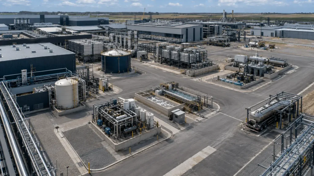
Place high-intensity treatment after avoidance, reduction, segregation and fit-for-purpose reuse.
Controlled principleThe hierarchy is not a promise that every project can stop at an upstream level. It is a disciplined order of investigation. Each level is tested against product quality, safety, regulation, operating reliability, water value, residual routes and total system burden before the project escalates to a more intensive response. |
|---|
10.1 A hierarchy prevents the project from starting at the most expensive end
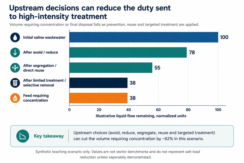
Chapter 9 closed the water, salts, reagents, products, solids, moisture, purge and accumulation across a named boundary. That closed balance is the starting point for strategy selection. The first question is not which high-recovery technology can process the full flow. It is how much of the flow and contaminant load should exist at all, which streams should remain separate, where water can be reused at lower treatment intensity and which constituent actually forces the next step.
EPA’s pollution-prevention framework places source reduction ahead of reuse, recycling, treatment and disposal, and the U.S. Pollution Prevention Act states that pollution should be prevented or reduced at source whenever feasible. EPA also notes that no single waste-management approach is suitable for all materials and circumstances. The ten-level hierarchy in this guide adapts those principles specifically to saline industrial wastewater; it is an engineering decision framework, not a universal legal hierarchy.
The hierarchy also prevents a false comparison between a complete ZLD train and an unchanged site. Source reduction, water efficiency, segregation and reuse can change both the hydraulic load and the chemistry sent to the final brine system. In some projects, the decisive improvement is a smaller, cleaner and more stable feed rather than a new final-stage technology.
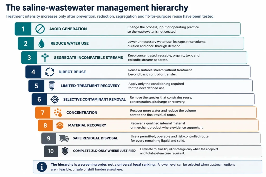
Figure 10.1. The ten-level saline-wastewater management hierarchy required by the master specification.
| Level | Management action | Primary objective | Evidence gate | Typical residual consequence |
|---|---|---|---|---|
| 1 | Avoid generation | Eliminate the wastewater source or pollutant formation. | Process change is safe, reliable and does not shift burden to another medium or location. | No stream, or a fundamentally smaller/cleaner one. |
| 2 | Reduce water use | Reduce unnecessary hydraulic volume and dilution. | Product quality, cleaning, heat transfer and worker/process safety remain protected. | Lower flow, potentially higher concentration; salt load may be unchanged. |
| 3 | Segregate incompatible streams | Protect reuse, recovery and simpler treatment routes. | Streams can be separately collected, stored, controlled and managed during upset. | Several defined streams instead of one mixed wastewater. |
| 4 | Direct reuse | Use a stream again without material treatment. | A named user accepts the available quality, quantity, timing and reliability. | Reduced discharge; purge or intermittent off-spec stream remains. |
| 5 | Limited-treatment recovery | Meet only the next-use specification. | Treatment target is fit for purpose and the new residual is manageable. | Recovered water plus a smaller treatment residual. |
| 6 | Selective contaminant removal | Remove the species that constrains the next step. | The constraint and removal mechanism are proven; sludge/product and carryover are closed. | Targeted sludge, concentrate, regenerant or product stream. |
| 7 | Concentration | Recover additional water and reduce residual liquid volume. | Scaling, fouling, corrosion, energy, availability and endpoint are acceptable. | Higher-strength concentrate, cleaning waste and sometimes solids. |
| 8 | Material recovery | Capture an internal-use material or qualified product. | Inventory, yield, purity, specification, user/buyer, legal route and fallback are credible. | Product plus impurity-rich mother liquor, wash and off-spec material. |
| 9 | Safe residual disposal | Manage the remaining liquid and solids within a permitted, operable route. | Capacity, logistics, monitoring, liability and upset route are demonstrated. | Managed liquid, sludge or solid leaves the defined process boundary. |
| 10 | Complete ZLD only where justified | Eliminate routine liquid wastewater from the stated boundary. | No acceptable routine liquid endpoint exists, or the integrated compliance/water-value case justifies the final step. | Solids, sludges, gases, cleaning wastes and non-routine streams remain. |
Table 10.1. Ten management levels, their evidence gates and the residuals that remain.
10.2 Level 1: avoid generation
Avoidance changes the production or service process so that the wastewater, salt addition or contaminant load is not created. Examples include dry or mechanical cleaning before washing, eliminating unnecessary quench or displacement steps, replacing a once-through operation, changing raw-material purity, preventing product loss, controlling spills, redesigning rinsing sequences and removing an unnecessary chemical addition.
EPA defines pollution prevention as reducing, eliminating or preventing pollution at its source before recycling, treatment or disposal. Its current industrial examples include process modification, less-toxic cleaning chemistry and water conservation. The important boundary is that an end-of-pipe unit that merely concentrates or transfers the same load is not source reduction.
Avoidance must be tested against the production objective. A process change that increases rejects, damages equipment, lowers hygiene, creates an air emission or transfers a hazardous constituent to a solid is not automatically superior. The burden shift must remain visible in the whole-site balance.
10.3 Level 2: reduce water use without hiding the salt load
Water reduction lowers the hydraulic duty through leak repair, shut-off control, counter-current rinsing, optimized spray or nozzle operation, dry cleanup, improved CIP endpoints, condensate recovery, cooling and boiler optimization, and better production scheduling. EPA’s Lean and Water Toolkit emphasizes factory-floor observation, water balances, root-cause analysis and matching water quality to the need.
A lower flow does not necessarily mean a lower contaminant load. If the same mass of salt, COD, oil or metal is discharged in less water, concentration rises and downstream equipment may face a more difficult feed. The project should report both volume reduction and mass-load reduction. Dilution elimination is valuable, but it must not be misreported as pollutant prevention.
| Reduction action | Water-volume effect | Load effect | Required check |
|---|---|---|---|
| Repair leaks and eliminate idle flow | Usually decreases flow. | Usually decreases water load; contaminant load may be unchanged. | Confirm the water was not performing cooling, sealing, flushing or safety duty. |
| Optimize rinse or CIP endpoint | Decreases batch volume and event duration. | Can reduce chemical and salt load if overdosing/rinsing is avoided. | Validate product cleanliness, hygiene and residual carryover. |
| Counter-current or cascade rinsing | Reduces fresh-water demand. | Can concentrate a smaller purge and improve recoverability. | Control cross-contamination and campaign changeover. |
| Replace once-through use | Reduces withdrawal and discharge. | Creates accumulation requiring a defined purge. | Close the recycle concentration and purge balance. |
| Remove dilution water | Reduces hydraulic flow. | Usually leaves pollutant mass unchanged. | Resize storage, pumps and treatment for the higher concentration. |
Table 10.2. Water reduction must distinguish hydraulic savings from contaminant-load reduction.
10.4 Level 3: segregate incompatible streams
Segregation prevents a manageable stream from becoming a complex mixed wastewater. A low-organic saline purge may be compatible with membrane or thermal concentration; the same purge blended with oil, solvent, chelant, active compound, metal-bearing wash or CIP waste may require a completely different front end. A concentrated batch can also be more valuable or easier to treat before it is diluted into the central system.
The decision is not simply to install more drains. The owner must define separate collection, tankage, level control, interlocks, campaign identification, sampling, off-spec diversion, operator responsibility and emergency overflow. Segregation that fails during upset is not a reliable design basis.
| Stream pair | Reason to segregate | Potential value protected | New requirement | Failure mode if mixed |
|---|---|---|---|---|
| High-salt / low-organic purge and high-COD wash | Organic load can foul membranes, foam thermals or contaminate crystals. | Water recovery and cleaner salt residual. | Separate drainage, tankage and event control. | Larger biological/oxidation duty and lower product quality. |
| Concentrated batch and dilute rinse | The concentrated fraction may be recoverable or cheaply hauled at small volume. | Product, solvent, acid/alkali or metal recovery. | Campaign identification and dedicated transfer. | Lost concentration advantage and larger treatment flow. |
| Acid and alkaline streams | Premature neutralization forms salts, heat and sludge. | Internal reagent reuse or selective metal recovery. | Compatible materials and controlled blending only where justified. | Uncontrolled precipitation and difficult mixed sludge. |
| Reusable cooling/condensate and contaminated process water | Cleaner stream may meet a direct or limited-treatment use. | High-value water reuse. | Protection from backflow and contaminated drains. | Unnecessary high-intensity treatment of clean water. |
| Routine stream and CIP/upset waste | Short events can control peak pH, COD, chelant, oxidant or surfactant duty. | Stable continuous treatment. | Event tank and controlled bleed or separate treatment. | Loss of biological, membrane, precipitation or crystallization stability. |
Table 10.3. Segregation protects simpler reuse, treatment, recovery and disposal routes.
10.5 Levels 4 and 5: direct reuse and limited-treatment recovery
Direct reuse is the transfer of a stream to a defined user without substantial treatment. Limited-treatment recovery applies only the conditioning needed for the next use: screening, cooling, pH adjustment, oil removal, filtration, softening, disinfection or another bounded step. Neither level aims to create the highest-quality water.
EPA defines fit-for-purpose specifications as the treatment requirements needed to bring a particular source to the quality required for health, environmental protection or the specific user. EPA’s industrial-reuse resources also note that industrial uses with limited human contact can require less costly and less energy-intensive treatment. The World Bank’s 2025 reuse report similarly frames treated used water as a reliable, climate-resilient supply when enabling regulation, investment and delivery models are in place.
The receiving process sets the specification. Quantity, timing, pressure, temperature, reliability and contaminants that accumulate in the receiving loop matter alongside analytical quality. A stream that meets an average concentration limit but arrives only during the wrong production campaign is not a secure reuse source.
| Reuse screen | Question | Direct reuse evidence | Limited-treatment evidence | Fallback |
|---|---|---|---|---|
| Quality | Which constituents constrain the user? | Available water already meets the defined envelope. | Treatment consistently meets only the required specification. | Diversion or blending route for off-spec water. |
| Quantity | Does donor flow match demand? | Sufficient overlap or storage exists. | Treatment capacity and storage match variability. | Alternative supply and overflow route. |
| Timing | Do production campaigns align? | Transfer logic handles schedule. | Equalization or batch treatment resolves mismatch. | Event storage or controlled disposal. |
| Reliability | What happens during outage? | User tolerates interruption or has backup. | Availability, redundancy and monitoring are defined. | Automatic backup supply and safe reject route. |
| Accumulation | What builds up in the receiving loop? | Purge balance is stable. | Selective treatment controls the accumulating constituent. | Named purge and endpoint. |
| Governance | Who owns quality and risk? | Responsibilities and acceptance criteria are agreed. | Sampling, alarms, release criteria and change control are documented. | Quarantine and incident protocol. |
Table 10.4. Fit-for-purpose reuse requires a named user, operating envelope and fallback.
10.6 Level 6: selective contaminant removal
Selective removal targets the species or property that prevents the next beneficial use, concentration step, product route or compliant discharge. It may remove hardness, sulfate, silica, oil, suspended solids, organics, a metal, a gas or a persistent contaminant. The objective is not to remove everything at once; it is to remove the first constraint at the lowest total system burden.
Selective removal is credible only when the limiting constituent, target residual concentration or load, removal mechanism, chemical additions, carryover, solids formation, regeneration waste, yield and downstream benefit are quantified. A precipitation reaction that removes calcium but creates an unmanageable wet sludge has not passed the hierarchy gate.
| Constraint | Selective response to screen | Downstream benefit to prove | Residual that must close |
|---|---|---|---|
| Hardness / carbonate | Softening, decarbonation, seeded precipitation or selective separation. | Higher stable membrane or thermal recovery; improved product purity. | Sludge, wash, filtrate and reagent-derived ions. |
| Sulfate / Ba / Sr | Targeted precipitation, NF/ED separation or another justified ion-management step. | Avoid sulfate scale or protect a product train. | Precipitate, membrane concentrate, regenerant or purge. |
| Silica / colloids | Coagulation, adsorption, seeded removal, pH control or solids separation. | Longer stable concentration path and cleaner heat-transfer/membrane surfaces. | Silica-rich sludge, spent media and recycle carryover. |
| Oil / organics | Source separation, flotation, coalescence, media, oxidation or biological treatment. | Protect membrane, evaporator, condensate or crystal quality. | Oily sludge, spent media, off-gas, biomass and oxidation residual. |
| Metal / target element | Selective precipitation, adsorption, ion exchange, extraction or electrochemical capture. | Compliance, reduced toxicity or qualified recovery. | Product/intermediate, regenerant, raffinate and off-spec material. |
Table 10.5. Selective removal is justified by the downstream constraint it removes and the residual it creates.
10.7 Levels 7 and 8: concentration and material recovery
Concentration recovers additional water and reduces the free-liquid volume requiring final management. It does not automatically reduce salt or contaminant mass. The choice among membrane, electrochemical, thermal and hybrid concentration depends on the chemistry, pressure or thermal duty, scaling/fouling controls, availability and final endpoint established in Chapters 8 and 9.
The Bureau of Reclamation’s concentrate-management work treats technology selection as a planning problem with site-specific weights, readiness and applicability, and recommends further desktop and pilot work for candidate options. That approach supports the hierarchy: concentration is selected to meet a defined residual-management objective, not because a particular technology is available.
Material recovery may sit before, within or after concentration. DOE defines water-resource recovery broadly as usable water, energy and materials, but this guide retains the stricter product gate from Chapter 3: presence is not recoverability, and recovery is not a bankable product. Internal use and avoided purchase are screened before merchant revenue.
| Level | Decision metric | Minimum proof | Downside case | Reason not to proceed |
|---|---|---|---|---|
| Concentration | Cost and burden per unit of useful water recovered and residual volume/load reduced. | Stable operation on design chemistry; closed energy, chemical, water and residual balances. | Higher energy, lower availability, earlier scaling and constrained residual route. | The remaining liquid already has a lower-cost, acceptable endpoint. |
| Material recovery – internal | Avoided purchase or avoided treatment/disposal cost. | Specification, consistency, internal demand, substitution approval and fallback. | Lower yield, variable quality or no internal demand during campaigns. | Recovered material creates more purification and waste burden than it avoids. |
| Material recovery – merchant | Risk-adjusted netback after purification, packaging, storage, transport and rejection. | Qualified buyer, legal route, product form, scale and off-spec disposal. | No buyer, lower price, rejected lots or product remains legally waste. | Revenue is needed to rescue an otherwise unviable treatment train. |
Table 10.6. Concentration and material recovery require separate technical and commercial gates.
10.8 Level 9: safe residual disposal is part of the strategy
The hierarchy does not treat disposal as design failure. Every real project retains liquids, sludges, solids, spent media, cleaning wastes, off-spec products or emissions that require a destination. A permitted and reliable residual route can make MLD the optimal solution; an unavailable or unacceptable route can make deeper concentration or ZLD necessary.
The endpoint should be screened for capacity, distance, acceptance criteria, pretreatment, monitoring, ownership, long-term liability, upset storage, weather exposure, closure obligations and cost escalation. Chapter 11 evaluates the individual disposal routes. Chapter 10 establishes the rule: no treatment train is selected until every routine and non-routine residual has a named destination.
10.9 Level 10: complete ZLD only where justified
Complete ZLD is the final hierarchy level because it eliminates routine liquid wastewater only by converting the remaining burden into recovered water, evaporation, solids, sludges, gases, cleaning wastes and managed non-routine streams. It can be the correct endpoint where no liquid route is available, where a specific legal or site condition requires it, or where the combined value of water recovery and avoided liability supports the final treatment increment.
The 2025 Nature Reviews Clean Technology assessment describes ZLD as maximizing water recovery and avoiding brine disposal but remaining expensive and energy-intensive, while MLD can be a practical lower-cost alternative where a residual disposal route exists. It frames technology selection as a constrained optimization problem dependent on location and regulation. This supports the booklet’s controlled position: ZLD is one endpoint, not the hierarchy itself.
A ZLD claim must state the boundary and account for outages, maintenance, start-up, cleaning, emergency storage, mother-liquor purge, condensate rejects and off-spec solids. A project that periodically hauls liquid off site has not achieved complete routine ZLD unless that stream is explicitly classified as non-routine and the claim boundary and frequency are stated.
ZLD justification testComplete ZLD proceeds only when upstream avoidance, reduction, segregation and reuse have been tested; the residual endpoint has been compared; the final water-recovery increment is technically stable; energy, chemicals, solids and emissions are visible; the downside economics are acceptable; and the system boundary permits an honest no-routine-liquid claim. |
|---|
10.10 Apply the hierarchy as a portfolio, not one linear train
A facility rarely has one wastewater and one answer. One stream may be directly reused, another may need selective oil removal, a concentrated batch may be hauled for recovery, a steady inorganic purge may feed an MLD system and a small hazardous stream may remain separately disposed. The optimal site strategy is therefore a portfolio of hierarchy positions.
The portfolio should be evaluated on a common annual and design basis. Avoid double counting: water saved through source reduction cannot also be credited as recovered water; a segregated product stream cannot also be counted as reduced pollutant mass unless the downstream destination is included; and a material recovered into wet cake cannot be reported as both product and disposal reduction without accounting for purity, moisture and rejection.
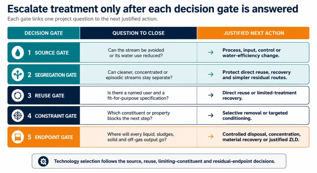
Figure 10.3. Evidence gates that turn the hierarchy into a project-development workflow.
| Option / stream | Hierarchy level | Annual water effect | Residual effect | Decision status |
|---|---|---|---|---|
| Process modification | 1 – Avoid | Water and wastewater avoided; basis stated. | Pollutant load avoided or transferred; transfer must be shown. | Implement / test / reject with reason. |
| Rinse optimization | 2 – Reduce | Withdrawal and discharge reduction. | Concentration and load changes stated separately. | Implement / test / reject with reason. |
| Clean condensate transfer | 4 – Direct reuse | Named user demand displaced. | Off-spec and overflow route stated. | Implement / test / reject with reason. |
| Selective hardness removal | 6 – Selective removal | May unlock higher recovery. | Sludge, reagent ions and filtrate closed. | Implement / pilot / reject with reason. |
| Membrane or thermal concentration | 7 – Concentration | Recovered-water basis and availability stated. | Concentrate, cleaning waste, energy and emissions stated. | Screen / pilot / FEED / reject. |
| Qualified salt or chemical | 8 – Material recovery | No automatic water credit. | Product, mother liquor, washing and off-spec route stated. | Internal qualification / buyer qualification / reject. |
| Permitted residual route | 9 – Disposal | No water-recovery claim unless separately demonstrated. | Capacity, compliance, logistics and liability stated. | Baseline / contingency / unavailable. |
| Final crystallization / drying | 10 – Complete ZLD | Net recovered water and evaporation stated. | All solids, purge, cleaning and non-routine streams stated. | Proceed only after full justification. |
Table 10.7. Portfolio register for documenting hierarchy position, water effect, residual effect and decision status.
10.11 Hierarchy acceptance gate
Before moving into detailed endpoint and technology selection, the project team should be able to show why each hierarchy level was implemented, advanced for testing or rejected. Rejection requires a reason tied to safety, product quality, regulation, operability, timing, economics, residual transfer or site constraints—not a preference for a downstream technology.
| Acceptance gate before Chapter 11The whole-site balance is closed; avoid/reduce opportunities are quantified; incompatible streams and non-routine events are segregated where justified; every reuse option has a named user and fit-for-purpose specification; the first limiting constituent is identified; concentration and recovery options have a defined purpose; and every remaining liquid and solid has at least one credible endpoint to compare. |
10.12 Chapter conclusion
The saline-wastewater management hierarchy places high-intensity treatment after the decisions that can remove or simplify the problem. Avoid generation first. Reduce unnecessary water use without confusing volume reduction with load reduction. Segregate streams before they destroy reuse, recovery or disposal options. Reuse water directly where the receiving process can accept it, and apply only the treatment required for the next use.
When a constituent blocks progress, remove that constraint selectively. Concentrate only for a defined water-recovery or residual-management purpose. Recover materials only when the product gate is satisfied. Treat safe residual disposal as a legitimate system endpoint. Proceed to complete ZLD only when the site, regulation, water value and lack of a credible liquid route justify the final increment.
The result is not one universal train but a site portfolio of actions at different hierarchy levels. Chapter 11 now compares the disposal endpoints that determine how far the hierarchy must proceed.
Chapter 10 in one sentenceZLD is one endpoint, not the hierarchy itself: prevent, reduce, segregate, reuse and remove the first constraint before escalating treatment intensity. |
|---|