
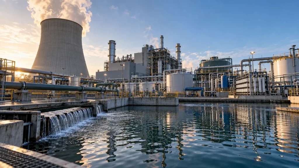
Utility integration, make-up-water value, blowdown chemistry and the residual route control the endpoint.
Controlled principlePower-plant saline streams are utility streams before they are brines. Reduce or segregate the source stream, value recovered water where it can replace make-up, and define the residual route before selecting concentration equipment. A generic ZLD train is not the starting point. |
|---|
Start with the power-station water circuit, not a generic ZLD train
Power and cooling sites can generate several saline streams that look superficially similar on a TDS sheet but serve different plant duties. Cooling-tower blowdown exists because evaporation concentrates make-up salts. Boiler or HRSG blowdown protects high-temperature steam-water chemistry. Wet flue-gas-desulfurization (FGD) wastewater is a purge from an air-pollution-control process and can carry high chloride, suspended solids, hardness, sulfate and trace contaminants. Combining these streams before screening their duties can destroy reuse opportunities, import incompatible chemistry and make the residual system harder to operate. [BC-36,1–3]
The sector decision sequence is therefore: optimize the originating utility; keep materially different streams segregated unless a mixing benefit is demonstrated; establish normal, design and upset chemistry distributions; identify internal water value and regulatory constraints; then select the least-complex endpoint that preserves generation or heat duty and has a finite residual route.
| Stream / duty | Primary reason it exists | First owner lever | Chemistry that commonly controls treatment | Endpoint question |
|---|---|---|---|---|
| Cooling-tower blowdown | Control dissolved-solids accumulation in an evaporative recirculating system. | Cycles of concentration, make-up quality, drift/leak control, side-stream treatment and alternate make-up. | Ca/Mg hardness, alkalinity, sulfate, silica, chloride, suspended/biological matter and treatment chemicals. | Can source reduction or internal reuse avoid a dedicated brine plant; if not, what residual route justifies MLD/ZLD? |
| Boiler / HRSG blowdown | Control boiler-water dissolved solids/sludge and protect steam quality. | Condensate return, feedwater quality, chemistry-based blowdown control and heat recovery. | Silica, conductivity/dissolved solids, alkalinity and chemistry program; pressure-specific limits belong to the boiler basis. | Can heat and water be recovered or cascaded before any saline concentration step? |
| Wet-FGD wastewater | Purge chloride and other accumulating species from the wet scrubber while maintaining FGD operation. | FGD recycle/purge optimization, equalization and pollutant-specific pretreatment. | TSS, Ca, Mg, sulfate, chloride/TDS, organics, trace metals and selenium/other regulated species. | Is the required endpoint discharge treatment, membrane-based MLD, encapsulation, spray evaporation or thermal ZLD? |
Table 37.1. Power/cooling streams should be screened by plant duty and chemistry before they are combined into one treatment problem.
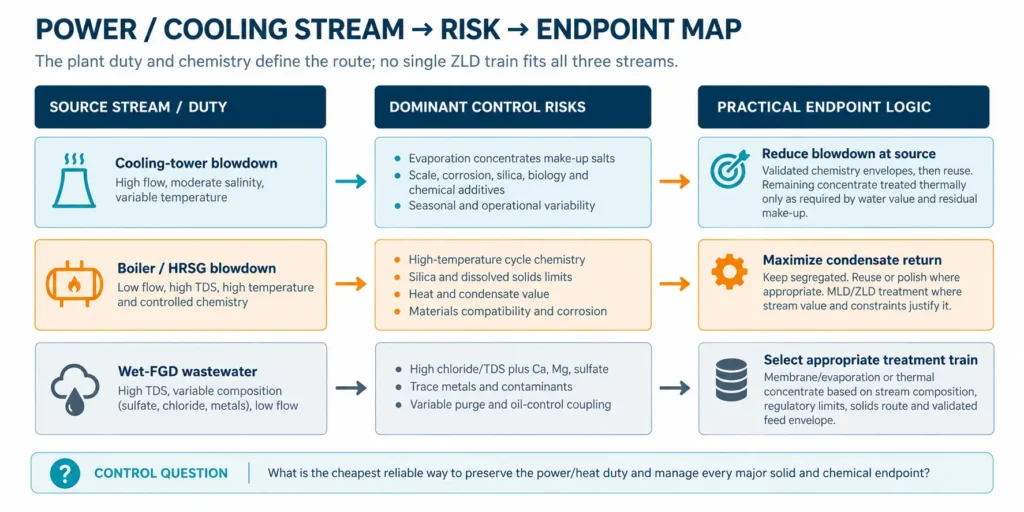
Figure 37.1. Power/cooling stream–risk–endpoint map. The visual is a decision map, not a universal technology train.
Cooling-tower blowdown: the first recovery lever is cycles, not downstream equipment
DOE cooling-tower guidance treats blowdown control as a primary water-efficiency lever. Water leaves the tower by evaporation, blowdown, drift and unintended losses; make-up replaces those losses. As water evaporates, calcium, magnesium, chloride, silica and other dissolved constituents remain and become more concentrated. Increasing cycles of concentration can reduce make-up and blowdown, but only within the chemistry and treatment envelope that avoids unacceptable scale, corrosion and biological or suspended-solids problems.
This source-reduction step matters to MLD/ZLD because every cubic metre of blowdown avoided is a cubic metre that does not need downstream concentration, residual storage or disposal. The economic value is site-specific: it depends on make-up-water cost and scarcity, the heat-rejection duty, water chemistry, chemical treatment, side-stream treatment and the final destination of the remaining blowdown.
| Balance field | Controlled definition | Measurement / evidence | MLD/ZLD consequence |
|---|---|---|---|
| Make-up, M | Water added to replace evaporation, blowdown, drift and other losses. | Make-up flow meter plus reconciled site balance. | Sets purchased/reclaimed-water demand and the source flow entering the cooling circuit. |
| Evaporation, E | Water evaporated to reject heat. | Heat/load or validated water-balance estimate. | Not recoverable as liquid blowdown; it is the functional water consumption of the evaporative duty. |
| Blowdown, B | Controlled purge used to limit dissolved-solids accumulation. | Blowdown flow meter and controller history. | Primary saline liquid available for reuse, discharge, MLD or ZLD treatment. |
| Cycles, C | Concentration ratio based on a conservative species or suitable indicator; conductivity ratio is a screening control, not the complete chemistry. | Make-up vs circulating/blowdown chemistry and flow cross-check. | Higher justified C reduces B, but the chemical limit must be validated rather than assumed from a generic set point. |
| Drift / leaks / overflow | Non-product water losses outside intentional evaporation and blowdown. | Inspection, meters and reconciliation. | Unaccounted losses distort cycles calculations and can hide a water-efficiency problem upstream of treatment. |
Table 37.2. Cooling-tower source reduction begins with a closed water balance and a chemistry-limited cycles basis.
Visible calculation for the scenario-only graph: if drift, leaks and dissolved-solids losses other than blowdown are neglected and evaporation is normalized to E = 1.0, then C = M/B, M = E + B, B = E/(C−1), and M = EC/(C−1). The curve demonstrates diminishing hydraulic benefit; it does not recommend any operating cycles or chemistry limit.
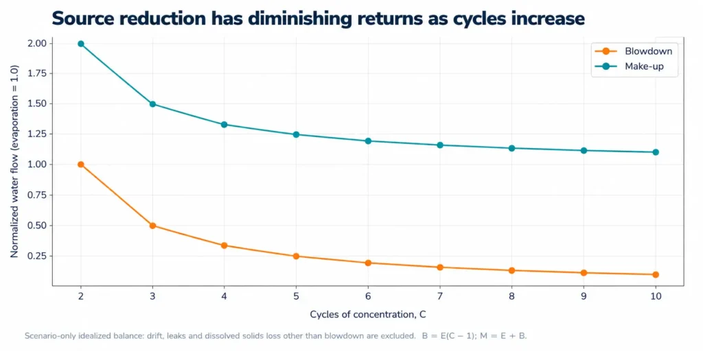
Figure 37.2. Scenario-only idealized cooling-tower water balance. Higher cycles reduce blowdown strongly at low C and progressively less at higher C; chemistry, drift and real losses are intentionally excluded.
Chemistry—not conductivity alone—sets the feasible cooling-tower envelope
Conductivity is useful for continuous blowdown control, but the concentration ceiling is established by the species and mechanisms that constrain the actual system. DOE guidance explicitly notes calcium, magnesium, chloride and silica accumulation and recommends determining the maximum safe cycles with a water-treatment specialist. It also identifies side-stream softening when hardness is limiting and compatible alternative make-up sources where they reduce fresh-water demand.
| Chemistry / condition | Risk as cycles increase | Evidence needed | Design response before MLD/ZLD |
|---|---|---|---|
| Ca/Mg + alkalinity | Carbonate scale and loss of heat-transfer performance. | Make-up/circulating distribution, pH/alkalinity, temperature and treatment program. | Optimize chemistry; consider softening or selective hardness removal if it creates whole-system value. |
| Sulfate + calcium | Sulfate scaling can become limiting after concentration or after another ion is removed. | Ion-specific saturation/speciation through the full cycles and downstream recovery range. | Do not infer safety from conductivity; stage selective precipitation/softening where justified. |
| Silica / silicate | Silica scale or difficult deposits can constrain both tower cycles and downstream membranes/thermal equipment. | Reactive/total silica method, pH, temperature, Mg/Al interactions and variability. | Set a chemistry-specific ceiling or validated silica-control step. |
| Chloride / corrosivity | Higher chloride concentration can raise materials and corrosion risk. | Metallurgy, temperature, pH, oxidant and deposit conditions. | Treat corrosion and recovery as a coupled materials decision. |
| TSS / dust / biology | Deposits and biofouling may limit operation even when dissolved chemistry appears acceptable. | TSS/turbidity, basin history, microbiological control, side-stream filtration performance. | Improve solids/biological control; side-stream filtration does not remove dissolved salts. |
| Reclaimed or process make-up | May reduce fresh-water demand but import nutrients, organics, silica, chloride or treatment chemicals. | Full blended make-up analysis and compatibility trial. | Credit alternate water only after the blended tower and downstream residual chemistry is checked. |
Table 37.3. The safe cycles envelope is mechanism-specific; conductivity is a control indicator, not a substitute for ion, fouling and materials analysis.
Cooling-tower blowdown architectures should follow water value and residual route
There is no universal “typical ZLD train” for cooling-tower blowdown. Once source reduction is optimized, the remaining route depends on reuse quality, scaling chemistry, discharge/disposal options, available utilities and the cost of the final liquid or solid residual. A membrane-led MLD route may be attractive when chemistry can be conditioned and a smaller concentrate has a viable endpoint; a thermal finish is justified only when the remaining liquid obligation requires it.
| Architecture | When it earns a screen | Core blocks / controls | Residual that remains | Failure check |
|---|---|---|---|---|
| Source reduction + direct reuse/discharge | Blowdown meets a lawful discharge or internal-use requirement after minor conditioning. | Cycles optimization, segregation, monitoring and fit-for-use polishing if needed. | Discharged or reused water; filter/chemical wastes. | Do not build a brine plant to solve a water-balance or permit issue that simpler controls can close. |
| Selective conditioning + membrane recovery | Water has reuse value and scaling/fouling species can be controlled. | Equalization, solids control/softening as required, RO/other justified membrane concentration, CIP and concentrate endpoint. | Concentrate plus pretreatment/CIP solids/liquids. | Confirm membrane feed envelope and cost the concentrate route. |
| Hybrid MLD | Residual disposal is costly/constrained but complete ZLD is not required. | Source reduction + selective conditioning + membrane/electrochemical/thermal concentration chosen to reduce residual burden. | Smaller liquid residual with defined storage/transport/disposal. | Do not label MLD by a universal recovery percentage. |
| Thermal ZLD finish | No routine liquid wastewater may leave the defined boundary or no viable liquid residual route remains. | Preconcentration where justified, evaporator/crystallizer, mother-liquor purge logic, solids dewatering/handling. | Sludge, crystals/salts, purge/cleaning wastes and emissions. | Prove solids logistics and utility availability; ZLD does not mean zero waste. |
| Internal cascade / alternate make-up integration | Recovered water can displace tower make-up or another site demand. | Quality matching, storage, blending and cross-contamination controls. | Any rejected/off-spec water and new concentrated residual. | Reuse value must be tied to the actual avoided water source and reliability requirement. |
Table 37.4. Cooling-tower MLD/ZLD selection is an endpoint decision after source reduction, not a predetermined equipment sequence.
Boiler and HRSG blowdown: optimize the steam-water cycle first
Boiler blowdown is a high-value utility stream because it contains both water and sensible heat, but its composition and allowable cycles are tied to the steam system rather than to a generic brine criterion. DOE guidance prioritizes condensate return, chemistry-based blowdown control, automatic chemical feed and blowdown heat recovery. Excessive blowdown wastes water, energy and chemicals; insufficient blowdown can contribute to deposits or carryover.
The MLD/ZLD implication is straightforward: first reduce the amount of high-quality make-up that becomes blowdown. Keep boiler/HRSG blowdown segregated from dirtier streams until the value of its heat and comparatively controlled chemistry has been tested. Only then should the residual enter a common saline-water treatment system.
| Priority | Owner action | Why it precedes a brine plant | Required evidence | Residual / integration decision |
|---|---|---|---|---|
| 1. Condensate return | Maximize reliable return of clean condensate and repair losses. | Reduces make-up water, treatment chemicals and heating duty simultaneously. | Return rate, contamination events, temperature/enthalpy and makeup quality. | Do not contaminate recoverable condensate by premature mixing. |
| 2. Blowdown control | Control blowdown from boiler-water quality rather than fixed excessive purge. | Reduces source volume without adding downstream equipment. | Boiler chemistry program, instrument reliability, operating/load distribution. | Define normal and upset blowdown separately. |
| 3. Heat recovery | Recover flash steam and/or sensible heat where site conditions support it. | Captures value before cooling/dilution. | Temperature, pressure, operating continuity and receiving heat sink. | Credit only usable heat at coincident demand. |
| 4. Water cascade / polishing | Reuse blowdown after appropriate cooling/polishing where receiving use allows. | Avoids both new make-up and disposal. | Fit-for-use water quality and receiving-system chemistry. | Track any concentrate or regenerant created by polishing. |
| 5. MLD/ZLD treatment | Combine with other saline streams only after compatibility is proven. | Prevents a utility-optimization problem from becoming an oversized brine-treatment project. | Combined mass balance, chemistry, residual route and outage basis. | Size on justified post-optimization flows, not historical uncontrolled blowdown. |
Table 37.5. Boiler/HRSG blowdown management should recover steam-cycle value before it is treated as a generic saline wastewater.
Wet-FGD wastewater is coupled to the air-control system
Wet-FGD wastewater should be treated as a purge from the scrubber chemistry and solids circuit, not as an independent wastewater generator. EPA’s 2024 Technical Development Document distinguishes FGD purge flow from an “optimized” flow and notes that increasing recycle can raise chloride; the practical purge is therefore constrained by plant-specific design and operating limits for the scrubber and associated materials.
For membrane treatment, EPA notes that pretreatment may be needed to remove excess TSS, calcium, magnesium, sulfate or organics to prevent scaling and fouling. Many FGD membrane pilots incorporated chemical precipitation, microfiltration or other pretreatment. Permeate can be reused or discharged depending on the regulatory and plant basis; concentrate still requires a defined endpoint such as encapsulation, injection where permissible, spray/thermal evaporation or another treatment route.
| FGD design variable | Why it moves | Treatment consequence | Evidence / control |
|---|---|---|---|
| Purge flow | Fuel/chloride input, scrubber recycle, gypsum/solids operation and load change. | Treatment plant sees a distribution, not one average flow. | Normal/design/upset purge, load/fuel scenarios and FGD operating limits. |
| TSS / gypsum fines | Hydrocyclone/clarifier performance, solids carryover and recycle. | Drives clarification/filtration, membrane fouling and solids load. | PSD/TSS, settling/dewatering, upset carryover and equalization. |
| Ca / Mg / sulfate | Limestone/lime chemistry, oxidation and recycle concentration. | Can control precipitation, membrane recovery and thermal scaling. | Full ion balance, speciation/saturation and real-feed tests. |
| Chloride / TDS | Fuel/sorbent impurities and recycle; purge controls accumulation. | Materials, osmotic pressure and downstream concentration duty. | Chloride distribution, density/TDS cross-check and material limits. |
| Trace metals / selenium / nitrogen species | Fuel and reagent chemistry plus redox/biological conditions. | May determine discharge-treatment train even when water recovery is not the primary objective. | Jurisdiction-specific permit basis and treatability testing. |
| Organics / treatment chemicals | FGD additives and upstream plant chemistry. | May foul membranes or interfere with precipitation/biological steps. | Additive inventory, TOC/COD characterization and real-feed testing. |
Table 37.6. FGD treatment must be designed from the scrubber operating envelope and pollutant-specific chemistry, not from TDS alone.
FGD discharge treatment, MLD and ZLD are different endpoint decisions
EPA’s 2024 evidence base illustrates why FGD technology claims require a maturity and boundary check. The Agency identified 30 pilot-scale membrane studies for FGD wastewater worldwide and 12 full-scale foreign installations, while noting limited data on some configurations and performance. EPA also identified three domestic and six non-U.S. spray-evaporation installations. These counts are evidence that several architectures have been demonstrated; they are not proof that a particular feed can meet a guarantee without site-specific pretreatment and integration.
Thermal integration can be decisive. EPA describes a full-scale adiabatic evaporator that operated for three years with clarifier pretreatment and evaporated the FGD wastewater, but the propane-fired operating and maintenance cost was too high and the system was replaced. The lesson is not that adiabatic evaporation “fails”; it is that heat source, plant integration and lifecycle cost belong inside the technology claim.
| Endpoint family | Water / pollutant objective | Typical control logic | Main new residual / interface | Evidence gate |
|---|---|---|---|---|
| Pollutant treatment + discharge | Meet site permit / BAT / ELG for specified pollutants without necessarily eliminating liquid discharge. | Equalization, precipitation/clarification, biological or targeted polishing as required. | Treatment sludge, spent media/chemicals and discharged effluent. | Permit-specific performance on representative FGD wastewater. |
| Membrane-based MLD | Recover/reuse water and reduce liquid residual volume. | Pretreatment/softening/solids removal followed by appropriate membrane stages; permeate reuse where valuable. | Concentrate, pretreatment sludge and CIP waste. | Long-duration real-feed recovery, scaling/fouling, cleaning and concentrate endpoint. |
| Membrane + encapsulation / disposal | Avoid liquid discharge by immobilizing concentrated residual in a compatible solid matrix where lawful. | Membrane volume reduction plus defined mixing/encapsulation and disposal route. | Encapsulated solid and associated ash/reagent demand. | Leachability, material availability, disposal acceptance and loss of alternate ash use. |
| Spray / flue-gas evaporation | Use available hot gas/heat to evaporate wastewater and transfer solids to an air/ash control route. | Pretreatment as required, atomization/evaporation, particulate capture and air-system integration. | Solids in fly-ash/particulate stream and air-system constraints. | Load range, corrosion/deposition, air permit, heat availability and ash destination. |
| Brine concentrator / crystallizer ZLD | Recover distillate and convert routine liquid residual to solids/purge inside the defined boundary. | Pretreatment, thermal concentration, crystallization, solids separation and mother-liquor control. | Crystals/salt, sludge, purge/cleaning waste; high utility duty. | Representative feed, heat/energy basis, materials, solids route and outage integration. |
Table 37.7. FGD “ZLD technologies” solve different endpoint and integration problems; maturity must be assessed on the complete boundary.
Regulatory endpoint is jurisdiction- and permit-specific
Regulatory claims in this sector are current-sensitive and should not be transferred between jurisdictions. In the United States, EPA’s 2024 supplemental Steam Electric ELG strengthened requirements for FGD wastewater and other coal-fired power-plant wastestreams. A final Deadline Extensions Rule published in December 2025 extended compliance deadlines; EPA states that the action did not change the zero-discharge requirements themselves and that implementation information may inform future rulemaking. The project basis therefore needs the current permit and rule status at the time of design.
In the European Union, Commission Implementing Decision (EU) 2021/2326 sets BAT conclusions for large combustion plants. For direct discharges from flue-gas treatment, the BAT-AEL table includes daily-average ranges such as TSS 10–30 mg/L, fluoride 10–25 mg/L and sulfate 1.3–2.0 g/L, with source footnotes and applicability qualifications that must be read with the installation-specific permit. These values are regulatory context, not generic MLD/ZLD design specifications.
| Regulatory basis | Current verified point | What it means for Chapter 37 | Do not infer |
|---|---|---|---|
| U.S. Steam Electric ELG | 2024 rule strengthened requirements for FGD wastewater, bottom-ash transport water and combustion-residual leachate; current requirements are implemented through permits. | Screen the exact wastestream, plant status, compliance dates and permit before selecting discharge vs no-discharge architecture. | That one national deadline or technology train applies to every power plant. |
| U.S. 2025 Deadline Extensions | EPA extended deadlines and states the action did not change the zero-discharge requirements themselves; future rulemaking may address implementation. | Treat schedule and regulatory trajectory as a live project risk; verify again at FEED/procurement. | That an extension eliminates the underlying treatment obligation. |
| EU LCP BAT conclusions | BAT 15 identifies combinations of wastewater-treatment techniques; BAT-AELs apply to direct discharge from flue-gas treatment at the installation outlet. | Use BAT conclusions and permit conditions to define the discharge endpoint and monitoring basis. | That BAT-AELs are universal product-water targets or automatically require ZLD. |
| EU examples from BAT-AEL table | Daily-average examples include TSS 10–30 mg/L, fluoride 10–25 mg/L and sulfate 1.3–2.0 g/L, subject to cited notes/applicability. | Carry the exact parameter, averaging basis, applicability note and permit into the design-basis register. | That the upper/lower values can be copied into another jurisdiction or wastewater without context. |
Table 37.8. Current regulatory evidence defines the required endpoint; it does not replace site-specific permitting or technology qualification.
Utility integration changes both the water balance and the economics
Power sites can create unusually strong internal reuse and heat-integration opportunities, but the timing and quality of those utilities must match. EPA notes that distillate/permeate from some FGD treatment configurations can be reused within the plant, including as FGD or cooling-related make-up. DOE similarly emphasizes condensate return and alternative cooling-tower make-up sources. The financial credit is therefore the avoided site water, heat or disposal cost—not an abstract “recovered water price.”
| Integration opportunity | Potential value | Boundary condition | Risk if credited too early |
|---|---|---|---|
| Recovered water → cooling make-up | Avoid fresh/reclaimed water purchase and reduce intake demand. | Quality compatible with tower chemistry; storage and flow coincide with cooling demand. | Reuse contaminants reduce allowable cycles or create new blowdown burden. |
| Recovered water → FGD / process use | Close an internal water loop and reduce discharge. | Receiving process tolerates dissolved/trace constituents and variability. | Water is “reused” but increases purge or reagent demand elsewhere. |
| Boiler blowdown heat recovery | Avoid boiler feedwater heating / recover flash steam. | Temperature/pressure and heat sink coincide; corrosion/materials controlled. | The model credits heat with no real receiving demand. |
| Flue gas / exhaust as evaporation heat | Reduce purchased thermal energy for FGD residual concentration. | Hot-gas availability over operating load, air-system compatibility and outage philosophy. | Waste-heat claim disappears at the exact load or outage state when treatment is needed. |
| Shared pretreatment / solids handling | Reduce duplicate equipment and staffing. | Streams are chemically compatible and shared asset has sufficient normal/upset capacity. | Common-mode failure disables multiple water and air-control systems. |
Table 37.9. Utility integration creates value only when quality, quantity, timing and reliability match the receiving plant duty.
ZLD moves burden to solids, purge, air systems and logistics
A no-routine-liquid-discharge endpoint changes the physical form and destination of the residual; it does not remove the burden. Power/cooling designs must therefore track softening sludge, FGD treatment solids, membrane concentrate, crystallizer solids, mother liquor, CIP waste, encapsulated material and any transfer of solids to fly ash or another air-control residue. Product claims remain separate: a recovered salt receives revenue credit only after specification, lawful status, qualification, logistics and a credible receiver are demonstrated.
| Residual | Where it originates | Quantity/quality control | Routine endpoint | Fallback question |
|---|---|---|---|---|
| Softening / precipitation sludge | Cooling or FGD pretreatment. | Dry solids, moisture, co-precipitated metals/silica, dewaterability. | Approved reuse or disposal route. | Can the plant store/dewater/dispose at peak and upset production? |
| Membrane concentrate | RO/NF/other membrane concentration. | Flow, density, ion load, organics and scaling species. | Further concentration, injection/disposal where lawful, encapsulation or other route. | What happens when downstream thermal/receiver is unavailable? |
| Crystals / mixed salts | Evaporator/crystallizer ZLD. | Phase, purity, moisture, mother-liquor retention and contaminants. | Qualified product or managed solid residual. | Is there full disposal capacity with zero sales revenue? |
| Mother liquor / purge | Crystallization impurity rejection. | Accumulation model, purge rate and hazard profile. | Recycle with controlled purge and named endpoint. | Does “closed loop” depend on zero purge? |
| CIP / cleaning waste | Membranes, evaporators, heat exchangers. | Batch volume, pH, chemistry, metals/scale and frequency. | Equalization/treatment/disposal route. | Can cleaning waste be handled during outage/upset without violating the claimed boundary? |
| Encapsulated / ash-associated solids | Membrane + encapsulation or spray evaporation. | Leachability, moisture, ash/reagent availability and transport. | Permitted landfill/use route. | Does treatment consume or contaminate a valuable ash/product stream? |
Table 37.10. A power-sector ZLD balance must name every solid, purge and cleaning stream and retain a no-product-sales fallback.
Operability must fit plant load, outage and compliance philosophy
Power plants are dynamic assets: load, fuel, ambient temperature, cooling demand, FGD duty and outage windows can all move the wastewater duty. A treatment system that is efficient at one steady-state point can still be unfit if it cannot preserve, bypass safely, store residuals or restart within the station’s operating philosophy. Chapter 35 therefore remains controlling: monitoring, laboratory capability, cleaning, spares, materials inspection and emergency storage are part of the sector design.
| Operating task / state | What changes | Monitor / record | Action trigger | Design provision |
|---|---|---|---|---|
| Load / seasonal cooling change | Evaporation, make-up and cooling blowdown flow/chemistry. | Make-up/blowdown flow, cycles, key ions, ambient/load. | Chemistry or capacity leaves validated envelope. | Turndown, equalization/storage and variable set-point logic. |
| Fuel / FGD chemistry change | Chloride, trace species, purge and solids characteristics. | Fuel/sorbent inputs, FGD purge chemistry, TSS/ions. | Feed outside treatment/permit basis. | Segregation, equalization and conservative upset route. |
| Treatment cleaning | Temporary capacity loss plus concentrated cleaning waste. | Normalized performance, pressure/flux/duty, cleaning effectiveness. | Validated cleaning criterion rather than fixed calendar alone. | Redundancy/storage, isolation and cleaning-waste route. |
| Station outage / FGD trip | Wastewater generation can fall abruptly while stored/residual streams remain. | Tank levels, preservation status, solids inventory, power/steam availability. | Storage or preservation limit approached. | Safe shutdown/preservation and restart sequence. |
| Residual receiver outage | Salt/sludge/encapsulated material cannot leave site. | Inventory, haulage/receiver status and storage capacity. | Finite buffer threshold. | Backup receiver or full-duration contingency storage/disposal. |
Table 37.11. Power/cooling treatment must be operable across the station’s load and outage states, not only at design-day steady state.
The MLD-versus-ZLD decision is a site optimization, not a sector default
The correct endpoint for a power/cooling stream is the one that satisfies the plant’s water, regulatory and residual obligations with the lowest defensible lifecycle burden. MLD can be the deliberate optimum when a small residual has a stable lawful endpoint. ZLD becomes justified when routine liquid discharge or disposal cannot satisfy the defined boundary, but the additional energy, chemicals, solids and operational complexity must remain explicit.
| Decision factor | Favors source reduction / reuse / MLD when… | Pushes toward ZLD when… | Evidence required |
|---|---|---|---|
| Make-up-water value | Recovered water has moderate value and a smaller residual can be lawfully managed. | Water scarcity/intake constraint makes additional recovery materially valuable. | Marginal avoided water cost and reliable receiving demand. |
| Liquid residual route | Discharge, injection, sewer/receiver or off-site route is permitted and robust. | No durable lawful routine liquid route exists within the stated boundary. | Permit, receiver capacity, transport and fallback. |
| Chemistry / scaling | Selective controls allow stable membrane/other concentration to a manageable residual. | Required endpoint still leaves a concentrate that must be thermally eliminated. | Real-feed pilot, mass balance, purge and materials basis. |
| Utility / heat integration | Additional thermal recovery is expensive or unavailable. | Reliable low-value heat/steam or strong integration reduces incremental thermal burden. | Load-duration availability and true marginal energy cost. |
| Solids / logistics | Solid generation from full ZLD would create greater handling burden than a stable liquid route. | Solid handling/disposal is more reliable than any liquid residual route. | Dry/wet solids quantities, dewatering, storage and disposal acceptance. |
| Owner capability / availability | Simpler train better fits staffing, support and outage philosophy. | Owner can operate/support thermal and solids systems with required redundancy. | O&M readiness, spares, cleaning and availability model. |
| Regulation / corporate boundary | Permit or internal target allows quantified residual liquid. | Defined no-routine-liquid-discharge requirement applies. | Current legal/permit/corporate boundary, not marketing terminology. |
Table 37.12. MLD and ZLD are endpoints selected from water value, chemistry, regulation, utilities, residual routes and owner capability.
Power/cooling sector acceptance gate
A sector concept should advance only when the originating utility has been optimized, the treatment basis reflects real operating distributions, every recovered-water and residual route is named, and the selected endpoint survives load, outage and regulatory downside cases. The gate is intentionally stricter than “technology can treat the sample.”
| Gate field | Proceed | Conditional / recycle | Stop | Required record |
|---|---|---|---|---|
| Source / utility optimization | Cycles, condensate return, FGD recycle/purge and stream segregation are optimized on a controlled basis. | One bounded optimization trial remains. | Brine plant sized on historical uncontrolled blowdown or mixed streams. | Utility water balance and source-reduction register. |
| Chemistry distribution | Normal/design/upset ions, TSS, additives and key pollutants are defined. | One non-fatal species/state awaits closure. | TDS/conductivity or one sample is the design basis. | Sampling, chemistry and operating-envelope register. |
| Treatment / recovery | Pretreatment and concentration limits are demonstrated against representative feed. | Scale-up item has finite test/contingency. | Vendor recovery or antiscalant claim replaces evidence. | Treatability/pilot and normalized performance package. |
| Residual / solids | Liquid, sludge, concentrate, crystal/purge and cleaning endpoints have finite routine and fallback capacity. | Backup route is time-limited but controlled. | Water service depends on assumed salt sales or indefinite storage. | Residual mass balance and capacity plan. |
| Utility integration | Recovered water/heat and shared assets have real quality, timing and availability matches. | Integration benefit is bounded pending operating confirmation. | Economic case assumes waste heat or reuse that is unavailable in the critical state. | Utility integration and marginal-value model. |
| Regulatory / permit | Current site rule/permit basis and compliance schedule are documented. | Known rulemaking/permit change is managed as a defined risk. | Architecture relies on obsolete or transplanted discharge limits. | Regulatory register and compliance pathway. |
| O&M / outage | Operators, monitoring, cleaning, spares, storage and restart fit station philosophy. | Early-life support closes a specific competence gap. | Treatment cannot preserve service through routine outage/cleaning/receiver failure. | O&M readiness and operating-state plan. |
Table 37.13. Power/cooling concepts advance only when utility, chemistry, treatment, residual, regulatory and operating boundaries are all auditable.
Stop ruleDo not size a power/cooling MLD or ZLD plant before the originating utility has been optimized. Stop or re-stage when chemically different streams are merged without a demonstrated benefit; conductivity substitutes for chemistry; a thermal case assumes heat that disappears at critical load; FGD treatment is decoupled from scrubber purge and air-control duty; or the residual/product route has no finite fallback. |
|---|
Handover to Chapter 38 — mining and metals
Chapter 38 shifts from integrated utility systems to mining and metals, where water value may be dominated by remoteness, dewatering, tailings integration, process-water quality, sulfate/metals chemistry and logistics. The common framework remains unchanged: start with the industrial water circuit, define the endpoint and residual route, design for chemistry distributions and fit the treatment system to the owner’s operating capability.
The power-sector lesson carried forward is methodological rather than technological. A stream cannot be judged from TDS, a vendor recovery or a generic ZLD train. Chapter 38 should therefore receive the same six controlled fields—source duty, site water value, chemistry distribution, process integration, residual route and operability—and reinterpret them for mine dewatering, hypersaline groundwater, acid mine drainage and tailings-water recycle.
| Power/cooling expression | Controlled lesson | Mining/metals translation for Chapter 38 |
|---|---|---|
| Cooling cycles and make-up quality | Reduce the source before treating the residual. | Mine-water segregation, contact-water control and process-water reuse before end-of-pipe concentration. |
| Boiler condensate return / heat value | Preserve higher-value streams and utility value before mixing. | Keep clean dewatering or reusable process water separate from metal/sulfate-rich or contaminated streams where beneficial. |
| FGD purge coupled to air-control duty | Treatment boundary is set by the industrial process that generates the wastewater. | Tailings, mineral processing and mine-plan constraints define water flow, chemistry and residual integration. |
| Power-station outage / load envelope | Operability and capacity must follow production states. | Seasonality, mine development, pit inflow, campaign operation and remote support must be included in the design distribution. |
| Residual solids / no-product-sales fallback | A water obligation cannot depend on speculative by-product demand. | Mineral recovery may be attractive, but tailings/disposal and water service must remain viable with zero product revenue. |
Table 37.14. Chapter 38 inherits the common decision controls, not the power-sector equipment train.
Chapter conclusion
Power and cooling systems demonstrate why MLD and ZLD should be designed from the industrial process outward. Cooling-tower blowdown first asks how much purge can be avoided by justified cycles and make-up management. Boiler/HRSG blowdown first asks how much condensate, heat and controlled water can be recovered inside the steam cycle. Wet-FGD wastewater first asks what purge is required for scrubber operation, which pollutants control the permit and what pretreatment, residual and utility interfaces are needed.
Only after those questions are answered does the concentration train become meaningful. A membrane route can reduce residual volume where scaling/fouling chemistry is controlled; thermal evaporation can close a no-liquid-discharge boundary where heat, materials and solids systems are viable; and MLD can be the stronger endpoint where a smaller liquid residual has a durable lawful route. In every case, recovered-water value and waste-heat credit must be tied to a real plant user, while salt/product revenue remains an evidence-gated upside rather than the foundation of the treatment obligation.
Chapter 37 in one sentencePower-sector MLD/ZLD is bankable only when the originating utility, chemistry distribution, regulatory endpoint, recovered-water value, residual route and outage/operability basis are designed as one plant system. |
|---|